Reports: DNI554784-DNI5: Size-Controlled Catalyst Nanoparticles Supported on Superacid-Derived Carbon Nanotube Foams for Synthesis of Clean Fuels
 printer friendly
Overview
With the ACS funding, we have made significant progress toward our project goal of establishing a rational basis for the development of a new catalyst with superior performance (higher activity, controlled selectivity, and longer lifetime) than current state-of-the-art catalysts used in Fischer-Tropsch synthesis (FTS). The conventional catalyst used in FTS is either Fe, Co or Ru often supported on SiO2 or Al2O3.1 There are fundamental problems associated with these catalyst supports that have hampered efforts in further improving the efficiency of FTS process. SiO2-supported Co catalysts are characterized by relatively low Co dispersion while Al2O3-supported Co catalysts are vulnerable to deactivation as the substrate reacts with Co to form a cobalt aluminate spinel.2,3 Also, the conventional supports have pores that are still largely limited to sub-nanometer scale, which limits mass transport of the reactants and products inside the catalyst matrix. Further, the heat produced during the exothermic FTS reaction is not well dissipated in the presence of these conventional catalysts due to the relatively poor thermal conductivity of SiO2 and Al2O3 supports, resulting in a temperature gradient in the packed bed reactors. To mitigate these problems and improve the FTS process, we are developing a 3D carbon nanotube (CNT)-based catalyst support that is characterized by high mesoporosity, high thermal conductivity and favorable catalyst-support interactions. Key highlights of our research achievements in the last one year include: (1) synthesis of highly monodispersed CNT-supported Fe catalysts via freeze drying, (2) activation of the new FTS catalysts at lower temperatures, and
(3) design and construction of a fluidized bed FTS reactor for testing the activity and selectivity of the synthesized catalysts.
Research Achievements
CNT-Supported Fe Catalysts Synthesized via Freeze Drying. The conventional methods for synthesizing catalysts typically involve a calcination step, which makes the control of the size distributions of the nanoparticles difficult. Co-precipitation is a common method for the synthesis of iron oxide nanoparticles because it is simple and allows for good control of the particle size distributions. The co-precipitation reaction can be written as:
Fe2+ + 2Fe3+ + 8OH- → Fe3O4 + 4H2O
To reduce ripening of the nanoparticles during synthesis, we have successfully replaced the calcination step with a freeze drying step. The catalyst synthesis process involve three steps. First, the CNTs were oxidized by refluxing with HNO3 (69 wt%) at 120° under magnetic stirring for 20h. Second, Fe3O4 nanoparticles were formed and deposited on the oxidized CNTs either by a one-step or a two-step process. The one-step process involved heating the CNT solution to 80℃ and adding FeCl2 (0.0118g) and FeCl3 (0.0322g) into the CNT solution followed by the injection of 1ml solution of NH3•H2O. The two-step process involved mixing the synthesized Fe3O4 nanoparticles and the oxidized CNTs. Third, the catalyst solutions obtained were cooled to -70° and freeze dried for 48h.
The XRD profiles in Figure 1 (A) for the samples obtained by our modified co- precipitation method are consistent with the profile of standard magnetite (Fe3O4), evidenced by characteristic peaks at 30° and 43°. The broad peak around 27° can be ascribed to the presence of CNTs. The XRD profile of Al2O3/Fe catalyst shows the characteristic peaks of Fe2O3 due to the oxidation of Fe3O4 during calcination. The calculated particle size from the Debye-Scherrer equation for CNT/Fe (one-step), CNT/Fe (two-step), and Al2O3/Fe are 9.2, 20.5, and 40.3nm, respectively. The SEM images in Figures 1 (B) and (C) reveal that the CNT/Fe (one-step) catalyst have particles that are well dispersed, whereas for the CNT/Fe (two-step) catalyst, the number density of particles appear lower and the CNTs are shorter. In general, the results reveal that ripening is decreased significantly by replacing the calcination step with freeze drying during synthesis of Fe catalysts via co-precipitation.
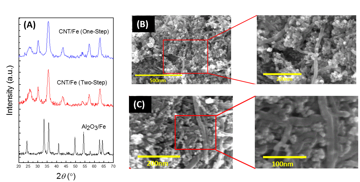
Figure 1. (A) XRD patterns of the various CNT/Fe catalysts and Al2O3/Fe catalyst; SEM images of CNT/Fe catalysts synthesized by a one-step process (A) and a two-step process (B).
Reducibility of CNT/Fe Catalysts. The reducibility of the synthesized catalyst was measured by temperature programmed reduction (TPR). The TPR profiles of CNT/Fe catalysts prepared by a one-step and a two-step process as well as Al2O3/Fe catalyst prepared by a one-step process are shown in Figure 2. There are four main peaks in the TPR profile of the CNT/Fe (one-step). The first peak at 310°C is ascribed to the reduction of Fe2O3 to Fe3O4 while the second peak at 360°C is ascribed to the subsequent reduction of Fe3O4 to FeO. The third peak at 520°C is attributed to the reduction of FeO to metallic Fe. Finally, the fourth peak at 590°C and the small peaks occurring at temperatures higher than 600°C are attributed to the gasification of the CNT support. For CNT-supported catalysts synthesized via the two-step method, only two peaks are observed. The peak at 490°C can be assigned to the reduction of Fe2O3 to Fe oxide species with a lower oxidation state. Conversely, for Al2O3/Fe catalysts, the reduction peaks are shifted to higher temperatures: the reduction of Fe2O3 to Fe3O4 occurs at 380°C; the small peak at 480°C is due to the reduction of Fe3O4 to FeO; and the final reduction of FeO to Fe occurs at 637°C. Therefore, in comparison to Al2O3/Fe, the temperature required to activate the CNT/Fe (one-step) catalyst is ~100°C lower.
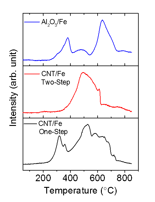
Figure 2. TPR profiles of various CNT/Fe catalysts and Al2O3/Fe catalyst.
FTS Experimental Setup. An experimental setup for evaluating the FTS activity and selectivity has been constructed following the design presented in Figure 3.
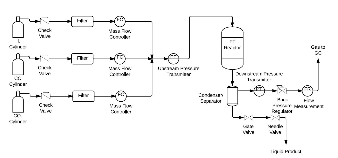
Figure 3. Schematic of experimental setup for FTS.
References
- Zhang, Q.; Deng, W.; Wang, Y. Journal of Energy Chemistry 2013, 22, 27.
- Khodakov, A. Y.; Chu, W.; Fongarland, P. Chemical Review 2007, 107, 1692.
- Jacobs, G.; Das, T. K.; Zhang, Y.; Li, J.; Racoillet, G.; Davis, B. H. Applied. Catalysis A: General. 2002, 233, 263.