Reports: DNI554217-DNI5: In Situ Characterization of Small Organic Molecule Oxidation Using Stimulated Raman Spectroscopy
Jin Suntivich, Cornell University
One of the largest cost and efficiency limitations of
electrochemical energy devices that convert organic molecules to electricity (e.g.
methanol, ethanol) lies in the slow kinetics of the small molecule
electro-oxidation at the anode. The ability to unravel the origin of this
sluggish kinetics can assist with the design and the discovery of new
electrocatalysts that can more efficiently facilitate the electro-oxidation
reaction; in addition, such knowledge can pave a way toward the design of a new
electrocatalyst that can utilize more difficult higher hydrocarbons for future electrochemical
energy conversions.
In an effort to address this challenge, our work has
been to create, develop, and apply an in situ characterization method
that can monitor and resolve the surface intermediate species during the electro-oxidation
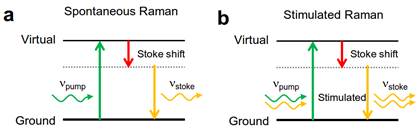
process. We utilize in situ stimulated Raman spectroscopy (SRS), which uses
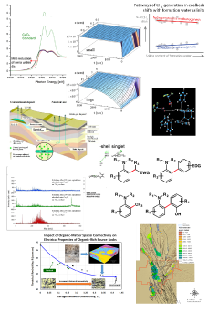
energy-matching photon to simulate the Raman scattering (Fig. 1). SRS has many advantages
over traditional in situ vibrational spectroscopy. Notably, the
challenge associated with infrared lies in the highly absorptive electrolyte. SRS
circumvents this challenge by using a visible/near-infrared probe, which is
electrolyte-transparent. In comparison to traditional Raman, SRS offers several
higher signal and better time resolution.
Generously supported by the ACS PRF, we have been
studying SRS for monitoring the electro-oxidation reaction in the past year. We
organize our effort into two objectives. The first focuses on creating an in
situ electrochemical cell. The second focuses on outfitting our Ti:sapphire
laser for SRS. In the first objective, we adopted the geometry of an electrochemical
cell that has been previously used for in situ (spontaneous) Raman
spectroscopy. This geometry uses an upward-facing electrode to minimize the
electrolyte signal while still retaining the benefit of a three-electrode cell.
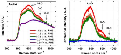
We have verified the efficacy of our electrochemical cell by reproducing the in
situ Raman features (e.g. Au-O and O-O) that are formed during the
electrochemical oxidation of Au (Fig. 2). These results confirmed that we had
successfully built a functional, in situ electrochemical cell that is
Raman-compatible.
After finishing with the in situ cell
creation, we turned our attention to outfitting our laser system for SRS. Our
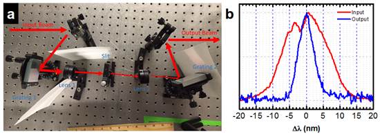
first task focuses on narrowing the spectral width of our laser, which has a bandwidth
that is too large for a Raman pump. To narrow down the bandwidth, we built a
spectral filter based on a stretcher-filter-compressor scheme, which allows us
to reduce the bandwidth to ~2.5 nm (Fig. 3). Our next step is to use an even narrower
slit to bring the bandwidth down to ~1 nm, which corresponds to ~17 cm-1
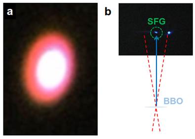
resolution. Our second task focuses on creating stable continuum generation as
a Raman probe. To accomplish this, we picked off and focused the Ti:sapphire beam
into a sapphire plate. This produces a white-yellow beam (Fig. 4a). We control
the quality of this generation by optimizing the power, the aperture, and the
focusing until the output looks visually stable and has the bandwidth needed to
serve as a Raman probe. Our third task focuses on creating a delay line to
ensure that the pump and probe arrived on the sample at the same time. We use a
beta-barium-borate (BBO) crystal to determine the delay length that can
synchronize this crossing (so-called ‘time-zero’). To find the delay, we carefully
adjusted the delay optics until we can observe the sum frequency generation
(SFG) between the two beams. At time-zero, the overlap between the two pulses
is maximized, thereby producing the highest SFG intensity (Fig. 4.) Our next task
is to integrate these individual components – an in situ electrochemicalcell, the pump and the probe pulse generation, and the delay optics to create
a functional, in situ SRS experiment to study the CO and methanol electro-oxidation
reaction.
Throughout this past 1-year period, this ACS-PRF
project has had incredible impact on my group’s research and education mission.
This impact extends beyond the scientific capability; both my career and my
student’s personal development had significantly benefited from this ACS-PRF
program. On the capability front, in addition to the progress abovementioned, this
program had allowed us to vastly improve our facilities. Through it, we had optimized
and built a functioning Raman system with the Ti:sapphire laser and identified
the temperature-humidity fluctuation in our laboratory. This latter finding had
allowed us to recently negotiate a new space with better temperature-humidity
control.
The impact the ACS PRF has on my career is
significant. It enables me to pursue a high-risk, high-reward direction that
integrates two normally distinct disciplines: non-linear spectroscopy and electrochemistry.
This pursuit allows me to test the hypothesis of whether we can combine advances
in spectroscopy and optics to drive discovery in catalysis. The impact on the
education of the students in my group is immense. This ACS-PRF program is directly
supporting a young, promising Cornell graduate student to learn cutting-edged concepts
and state-of-the-art skills in in situ spectroscopy, surface science,
and electrochemistry. The graduate student supported by the ACS PRF has also taken
on a mentorship role of a younger undergraduate, who is sponsored by the
research fund from Cornell. Together, they have built a highly collaborative
team, where they are learning how to work together and be analytical,
tenacious, and rigorous.
Figure
1. (a)
Traditional Raman scattering occurs via the spontaneous emission of the Stoke
transition. (b) Stimulated Raman Spectroscopy uses a separate, energy-matching
pulse to stimulate the emission.
Figure
2. In situ Raman spectroscopy on
Au electrode in 1M HClO4 (left). The differential Raman spectra
(right) shows the growth of the Au-O and O-O peaks at higher electrochemical
oxidation as reported previously.
Figure 3. (a)
A spectral filter for reducing the bandwidth of the Ti:sapphire laser. (b) Our
filter narrows the bandwidth from ~8 nm to ~2.5 nm.
Figure
4. (a)
Continuum generation using the Ti:sapphire laser. (b) At time-zero, both the
pump and probe pulses arrive simultaneously, allowing the sum frequency
generation (SFG) to occur. The middle blue spot is the result of the SFG (the
right blue spot is the second harmonic generation of the pump). BBO:
Barium-borate crystal.
 printer friendly