Reports: UNI852300-UNI8: A Field-Based Geomechanical Study of the Formation, Deformation, and Internal Structure of Reservoir-Scale Sandstone Dikes, Sheep Mountain Anticline, WY
W. Ashley Griffith, PhD, University of Texas Arlington
This
grant has supported a mix of field work, travel to national conferences,
tuition, and stipend for an M.S. student, Jennifer Beyer, and, during the first
year of the project, undergraduate student Monet Alvarado. During the second
year of the project, results were presented at the 2014 GSA Annual Meeting in Vancouver,
B.C. Additional results have been presented at the 2014 AAPG Student Expo in
Houston and the ACES student research symposium at UT-Arlington in the spring
of 2014 and 2015. Jennifer Beyer is now enrolled as a PhD student working with
Dr. Michele Cooke at the University of Massachusetts. A manuscript, Downward
propagating sandstone injectites at Sheep Mountain Anticline, WY: A case study
of natural hydraulic fracture containment, summarizing the results of the
work supported by this grant, and forming the basis of Jennifer’s MS thesis,
will be submitted to Geosphere within the next few weeks. An excerpt of
the current draft of the manuscript is included on the following pages. In
this excerpt, we are examining vertical profiles of injectites that propagated
downward, and using these to understand the fluid overpressures associated with
their formation.
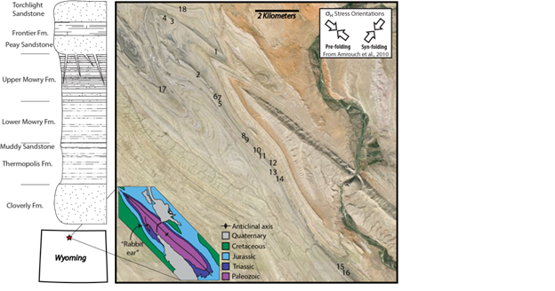
Sheep Mountain Anticline (SMA)
offers unique exposures of sandstone injectites that have been subsequently
deformed (Figure 1, Figure 2). We characterized injectites at SMA located
around the nose and west flank of the fold.. These injectites were sourced by
the Peay Sandstone of the Frontier Formation and propagated downward into the
Mowry Shale Formation in orientations consistent with the two major joint sets
found throughout the field area. Sand injection was driven by overpressurized
pore fluids in the Peay Sandstone.
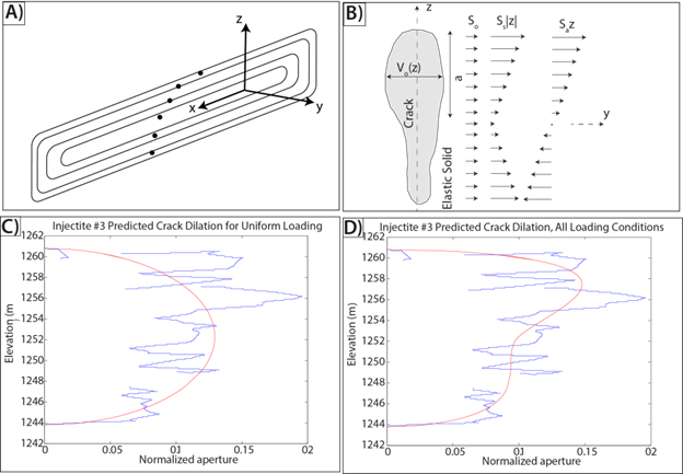
In
order to gain insight into the controls on downward injectite propagation, we
modeled the injectites at SMA as single-segment vertical blade-like cracks
(Figure 3a) because all injectites are roughly tabular bodies, longer laterally
than they are tall (Table 1). Using vector position data obtained while
mapping the injectites, the apertures for each injectite were plotted as a
function of elevation (Figure 3c). We considered three simple contributions to
crack loading (Figure 3b), for which analytical solutions are available: a
uniform normal stress, a linear normal stress gradient resulting in a
symmetrical stress distribution, and a linear normal stress gradient resulting
in an asymmetric stress distribution (Delaney and Pollard, 1981; Lachenbruch,
1961; and Pollard and Muller, 1976).
For a vertical 2D dike with half
length, a, position along the dike, z, and aperture, vo,we
define dimensionless variables Z = z/a and D(Z)=vo/a. In this coordinate system, the
origin is fixed at the center of the injectite, and the positive y-direction is
up (Figure 3b). The opening distribution along the crack can be written as:
, (1)
where
(2)
(3)
, (4)
and
, (5)
Here
So, Ss, and Sa are the
uniform, linear symmetric, and linear asymmetric overpressure distributions
respectively (Figure 3b). The total pressure distribution is a sum of the three
loading conditions, such that:
. (6)
Because
we lack tight constraints on in situ compliance, represented by (1-ν)/a,
exact magnitudes of the calculated overpressure gradients are less important
than the general trends in the gradients. We determined the relative
contribution of each loading condition (Table 1) to the total overpressure
distribution within the injectites using a multiple-linear regression model.
The predicted dilation calculated
as a function of the three loading conditions (Figure 3d) better predicts the
opening distribution than when calculated from only uniform loading (Figure 3c),
indicating the vertical pressure distributions were non-uniform. Pressure
profiles were calculated for seven of the eighteen injectites (Table 1).
Injectite
Average Injectite Strike (deg)
Height (m)
Length (m)
Max Aperture (m)
C1
C2
C3
3
N35E
58.3
234.7
1.66
-0.0022
0.1008
0.0605
8
N05W
142.9
217.3
2.7
0.0135
0.0016
0.0025
9
N53E
82.2
175.7
2.71
-0.0016
0.0212
0.02
10
N60E
7.7
31.1
0.44
-0.0171
0.0702
0.0136
13
N21W
43.1
60.0
1.66
-0.0071
0.1029
0.0538
15
N50E
10.3
30.4
0.87
0.0237
0.0888
0.0067
17
N71E
30.0
220.2
2.54
-0.0269
0.0586
0.0189
Table 1
In most cases, the constant C1
is negative while the constants C2 and C3 are
positive. Because C1 and C2 are symmetric
terms, and C3 is positive, this implies that the driving
stress (fluid overpressure) is largest near the top of the injectite; however
because C2 is non-zero, this gradient is not constant. Given
the heterogeneity of the upper Mowry formation, the assumption of uniform
material compliance is probably unreasonable. Therefore, although part of this
trend is likely due to the actual fluid overpressures in the dike, some may be
due to variations in effective elastic properties, cohesion, or inelastic
deformation along the fault (e.g., Burgmann et al., 1994; Willemse and Pollard,
1998; Martel, 1999).
In addition, the pressure maxima
occurring near the tips imply large stress intensities there. If the
injectites exploited pre-existing joints, we would expect near-zero stress
intensities near the injectite tips, consistent with an opening distribution
that asymptotically approaches zero near the crack tips, similar to the
bell-curve displacement distribution that results from cohesive endzone models.
What we observe instead are blunt ends to the opening distributions (Figure 3
C, D), consistent with stress intensity factors larger than those predicted by
the simple uniform loading case. In the field injectite segments can be found
exploiting joints and bedding discontinuities, but otherwise cross-cutting
bedding layers. Therefore we conclude that the injectites either forcefully
connected previously discontinuous joints confined to individual mechanical
layers, or they formed at the same time as the joints, contrary to previous interpretations.
Figure
1 – Injectites crop out in the Lower Cretaceous Upper Mowry Formation.
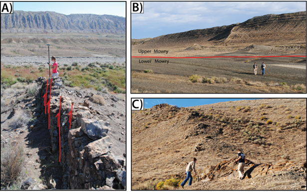
Figure
2 – Three examples of injectite outcrops.
Figure
3 – (A) Blade-like crack idealization. (B) Cross-section of a crack subjected
to uniform normal stress, symmetrical linear stress gradient, and asymmetrical
linear stress gradient (Modified from Delaney and Pollard, 1981). (C) Predicted
crack dilation for Injectite #3 under uniform loading. (D) Predicted crack
dilation for Injectite #3 as a function of all three loading conditions.
 printer friendly