This project targeted both
preparation of unique multifunctional substrate-supported elastomeric polymer
nanocomposite membranes (PNMs) and their application
in desulfurization treatment using thiophene/hexadecane mixture as a model
fuel. The major goals of this project were to prepare PNMs with enhanced
mechanical property, followed by the performance test in removing sulfur
compounds from model fuel. Polysulfone (PSU) supported polydimethylsiloxane (PDMS)/CNTs
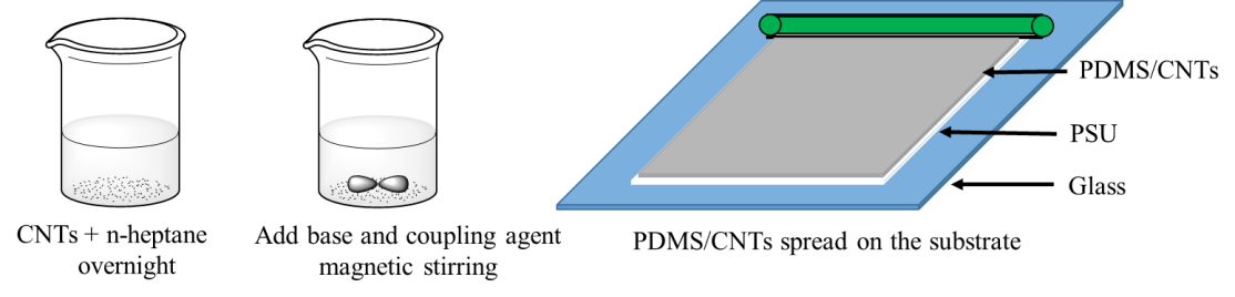
PNMs have been successfully synthesized by a direct mixing method followed by tempered
spreading and thermal curing, Scheme 1. Other major accomplishments are:
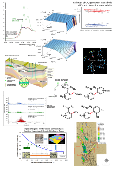
(1) Solvent effects on PNMs and thermal
and dielectric properties of PNMs have been investigated; (2) A facile method
has been developed to determine the concentration of sulfur compounds from the
model fuel; (3) Surface treatment of nanoparticles has been achieved to produce
polymer nanocomposites with uniform particle distribution; (4) Pervaporation
system has been assembled to fulfill desulfurization process.
Scheme
1. The procedure
of PDMS/CNTs PNMs synthesis
1. Characterization and analysis
of the membranes 1.1 Solvent
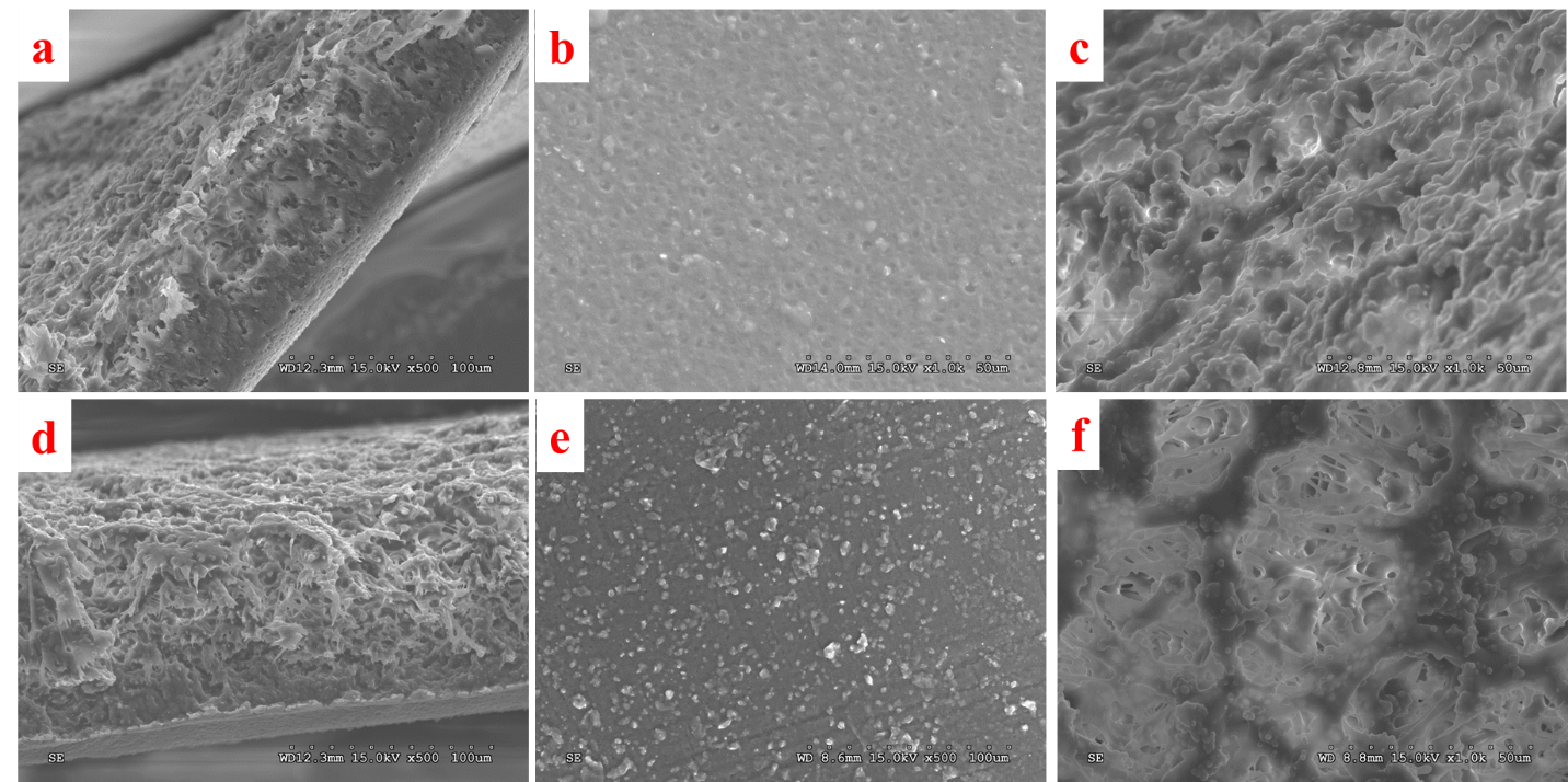
effects on PSU supported neat PDMS membranes Figure
1 shows the effect of two solvents (ethyl acetate and n-heptane) on PSU
supported neat PDMS membranes. a&d, b&e and
c&f images present the cross-section, top surface (PDMS)
and bottom surface (PSU) of the membranes, respectively. Comparing the cross-sections
of the membranes made from two different solvents (a&d), the most obvious distinction is that it is single layer from ethyl
acetate while double layer with higher pore density from n-heptane. The main
reason is that PDMS has higher solubility parameter in ethyl acetate (9.0 cal1/2cm-3/2)
than that in n-heptane (7.4 cal1/2cm-3/2),1which also results in
pores on the top surface of the membrane from ethyl acetate solvent, Figure b.
Moreover, the bottom surface of the membrane from ethyl acetate is much rougher
than that from n-heptane, Figure 1, c&f.
Figure
1.SEM microstructures of PDMS/PSU membranes
made from ethyl acetate (a-c) and n-heptane (d-f). a&d, b&e and
c&f images depict the cross-section, top surface (PDMS) and bottom surface
(PSU) of the membranes, respectively
1.2
Thermogravimetric analysis (TGA)
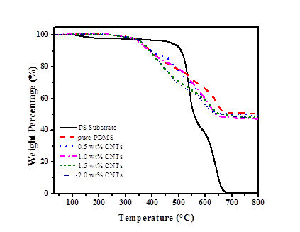
Figure
2. TGA of PSU
substrate, neat PDMS and PNMs, with CNTs loading of 0.5, 1.0, 1.5, and 2.0 wt%.
Table 1. Onset temperature T1onset
and T2onset of the PSU substrate, neat PDMS and the PNMs
Thermal
decomposition curves of PSU substrate, neat PDMS and PNMs under air atmosphere are shown in
Figure 2. The detailed thermal decomposition temperatures are shown in Table 1.
T1onset and T2onset are defined as the temperature at 10
and 20 wt% loss of the tested specimen, respectively. For the neat PDMS and PNMs,
there is a sharp weight loss stage in the temperature range from 350 to 700 °C,
which is caused by the chain breakdown of the PDMS
structure. The T1onset values (Table 1) indicate that introduction
of CNTs caused no obvious difference; however, the T2onset value
decreases with increasing CNTs loading due to the high thermal conductivity of CNTs which
facilitate the heat transfer to the inner part of the polymer.1.3 Dielectric property
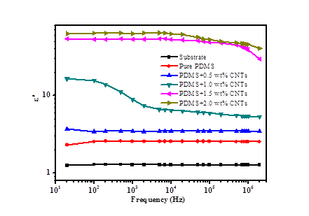
Figure 3. Real permittivity (ε´) of PSU substrate, neat PDMS and PNMs with
CNTs loading of 0.5, 1.0, 1.5, and 2.0 wt%, respectively
For the dielectric
property study, effects of the CNTs loading on the real permittivity (ε´)
of PNMs are shown in Figure 3. The PSU
substrate, neat PDMS and PNMs with 0.5 wt% CNTs loading are observed to have a
constant ε´ in all the frequency range. For PNMs with 1.0, 1.5 and 2.0 wt%
CNTs loading, the ε´ value decreases with increasing oscillation
frequency, which indicated a dielectric relaxation behavior.2
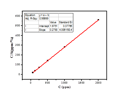
2. Absorbance
measurement at 226 nm by UV-vis spectrometry
C(ppm)
A
C/A
62.5
3.069
20.36494
125
3.449
36.24239
250
3.512
71.18451
500
3.526
141.8037
1000
3.552
281.5315
2000
3.568
560.5381
Table 2. Summary of concentration (ppm) of
thiophene in thiophene/hexadecane mixture and corresponding absorbance (A) at
226 nm
Figure 4. Calibration curve with R2
= 0.99999 and equation C/A=0.27932 C+1.97519
In this project,
UV-vis spectrometry is employed to determine the
concentration of thiophene in thiophene/hexadecane mixture. A calibration curve
was constructed by measuring the absorbance at 226 nm for different concentrations
(62.5, 125, 250, 500, 1000 and 2000 ppm), followed by plotting C/A against C. The
high R2 value indicates that this method is reliable for
quantification across the range of 2000 ppm thiophene.
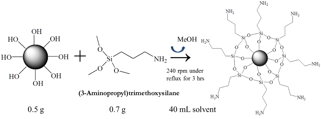
3.
Nanoparticle surface treatmentNanoparticles
were functionalized according to the following scheme to facilitate uniform
dispersion and strong particle-polymer interactions, thus improve sulfur
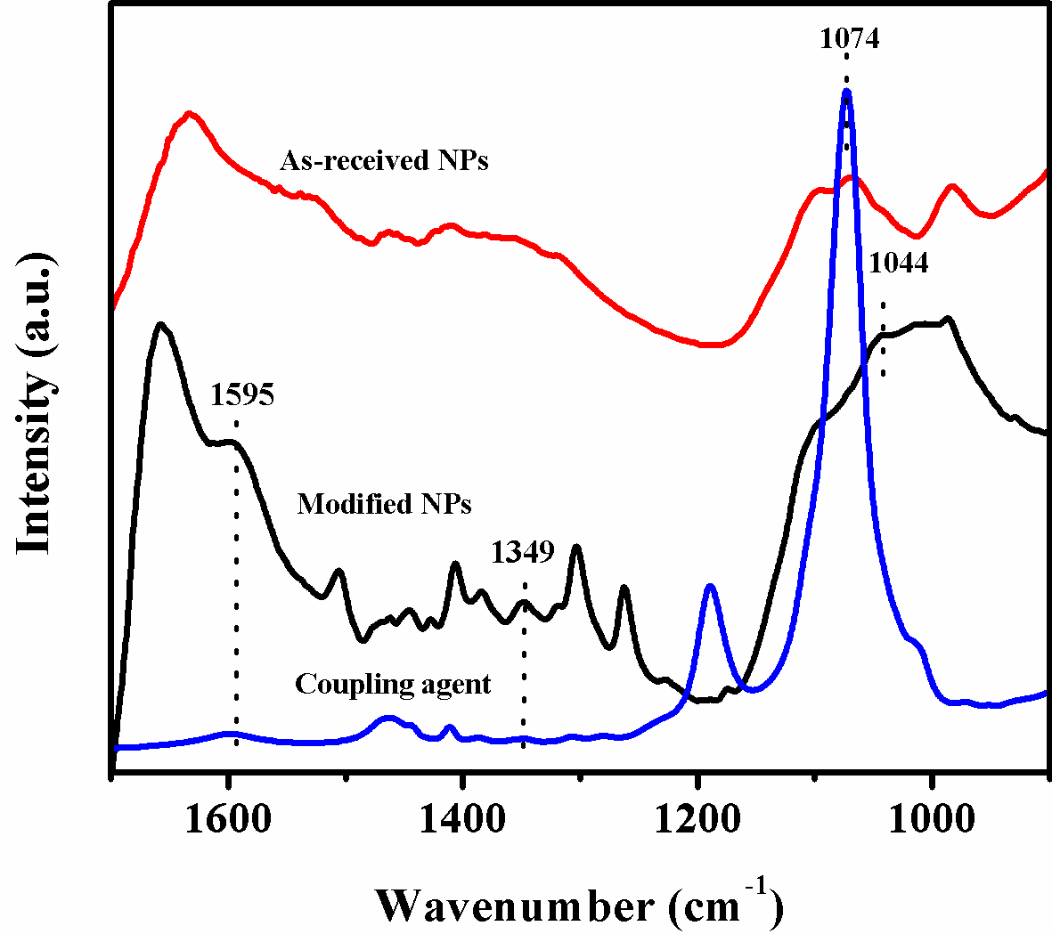
compound transportation and fuel processing yield. The functionalization was
verified by FTIR in Figure 5, in which the strong absorption peak at 1074 cm-1
is corresponding to Si-O-C bond in the curing agent, while for modified NPs,
three representative peaks were observed, namely Si-O-Si, Si-C and N-H bands at
1044, 1349 and 1595 cm-1, respectively.
Scheme
2. Silanization
of the hydroxyl group functionalized nanofiller.
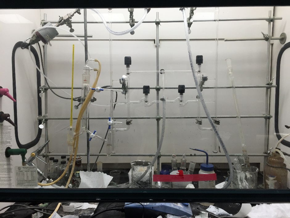
Figure 6. Pervaporation system
Pervaporation
system has been successfully assembled to achieve desulfurization process as
shown in Figure 6. The flow rate and solution temperature can be well
controlled by flow meter and heater, respectively.
In
summary, PNMs preparation has been accomplished and the following work will be
pursued to test the desulfurization performance and the results will be used to
guide further optimization.
a) Thermal properties will be
investigated by TGA/DSC.
b) Mechanical properties will be
assessed by tensile test machine following the ASTM standard.
c) Morphology of nanofiller and
membranes will be studied by SEM, transmission electron microscopy (TEM) and
atomic force microscopy (AFM).
d) Particle-polymer interactions
will be further investigated by X-ray fluorescence elemental mapping, X-ray
diffraction (XRD) and X-ray photoelectron spectroscopy (XPS).
e) Thiophene/hexadecane will be used
to study desulfurization capacity of PDMS and the PNMs.
In addition, we have done some
related work in membrane separation:
a) lab synthesized bio-inspired
CO2-philic network membrane for sustainable gas separation; and
b) novel polyamide (PA)
thin-film-composite (TFC) nanofiltration (NF) membranes (TFC NF) which have
achieved dual resistance to fouling and chlorine.
 printer friendly