Reports: ND953711-ND9: Characterizing Fuel Drop Vaporization at High-Pressure Environments
 printer friendly
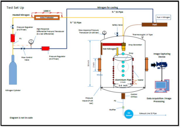
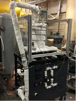
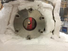
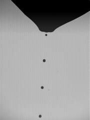
This project is to conduct fundamental research on characterizing fuel drop vaporization at realistic combustion chamber environments. The completed research tasks include the design and construction of the test system, including the test chamber, drop generation system, ambient gas supply and heating system, camera and laser, image acquisition system, and data analysis system. The schematic of the test system is shown in the first figure. The hardware is shown in the second figure, and viewing optical window can be seen in the third figure. The details of various components will be discussed later. Currently the system is operated at atmospheric pressure and temperature condition. A sample image of the fuel drop string is shown in the fourth figure.
A constant-volume, high-pressure, high-temperature test chamber was designed and manufactured. The test chamber was built using a 0.68-inch thick stainless steel cylindrical section rated to pressure of 45 bar. Two hemispherical radiative type ceramic heaters, 425 W and 120 V each, were placed inside the test chamber to produce the uniform ambient temperature around an aluminum cylindrical section. This section, 6 inches height and 2 inches diameter, was bolted in between the two ceramic heaters to act as a drop vaporization zone inside the test chamber. Four circular optical windows were built in the test chamber to visualize the drop stream. Quartz glasses were properly secured in these windows using stainless steel circular flanges and O-ring seals. Multilayer ceramic insulations were wrapped outside the test chamber and a layer of insulation was sheathed inside the chamber to minimize the heat loss. An aluminum foil envelope was used in the outside insulation layer to prevent any radiative losses.
A piezoelectric-based drop generator was mounted above the aluminum cylindrical section to generate spherical drops in the size range of 40-100 micron in diameter. It should be noted that different orifice tips can be used to generate different drop sizes. A characteristic waveform (pulse) was sent using a voltage amplifier and a pulse generator to generate the drops. Different parameters, such as drop spacing and drop diameter, can be controlled using the pulse generator. Three electric feedthroughs capable of withstanding high temperature were fitted on the top end cap of the vessel to supply voltage to the drop generator using an arbitrary waveform and high voltage amplifier. Fuel under pressure was supplied from a fuel reservoir to the drop generator. Fuel filter (7 micron) is always used before the orifice tip to prevent coagulation.
In the experiment, pure nitrogen, an inert gas, is supplied to the test chamber through an 8 kW, 240 V stainless steel inline preheater. The preheater can withstand high pressure and generate a maximum temperature of 760 .C. Preheater heats the incoming gas instantaneously and also safely raises the temperature up to the desired value at low flow rates. However, heating elements may burn if operated at very low flow rates. The heater was insulated on the outside using 1-inch thick ceramic blanket. Ceramic insulated stainless steel tubes of 3/8-inch size connects the preheater outlet to the test chamber inlet. The ceramic heaters heat the preheated nitrogen within the test chamber. The mass flow meter is used to measure and control the gas flow rates. Flow rates can be appropriately selected to produce stagnant and laminar flow conditions. The gas pressure inside the chamber is varied using gas regulators. However, it is essential to maintain a differential pressure (not exceeding 100 mbar) across the drop generator tip. Higher pressure differential immediately may result in the orifice tip failure. Therefore, a pressure controlling concept was developed to maintain the required differential pressure across the drop generator.
The high-pressure hot gas vaporizes the drops in the drop vaporization zone. The high-speed camera will capture the vaporizing drop images in the TIFF format. The camera is properly calibrated before the experiments using a Ronchi ruler (10 lines/mm). An image processing code developed in Matlab is used to analyze the various characteristics of the vaporizing drop such as drop diameter and drop spacing using edge detection technique to complete the analysis. A pressure transducer and an oxygen sensor continuously measure the chamber pressure and oxygen content. A safety valve and a ventilation valve were mounted on the test chamber top for safety consideration and ventilation of the fuel vapor, respectively. Temperature of the hot gas from the pre-line heater outlet and in the drop vaporization zone is continuously monitored using two K-type thermocouples.
It should be noted that in the original proposal the high chamber temperature and pressure would be achieved by combusting a premixed mixture, consisting of N2, O2, C2H2, and H2 with appropriate composition to reach desirable temperature. Such an approach appears to be overly complex and ineffective because only one test can be conducted each time. Then, the chamber needs to be emptied and recharged with premixed mixture for the next experiment. Therefore, we have modified the method of achieving high temperature and pressure by charging the chamber with high-pressure heated nitrogen. In this way, once the chamber is charged properly, desirable temperature and pressure will be maintained, and continuous experiments can be conducted without interruption. The new design is more effective, allowing more experiments to be conducted. However, the change in the design has caused a delay in this research. It is possible that an extension of this project may be requested in the near future, depending on the progress of the experiments.