Reports: ND955600-ND9: Hydrodynamics, Mass Transfer Parameters and Modeling of a Microchannel Reactor for Fischer-Tropsch Synthesis
 printer friendly
When natural gas (mostly methane) is produced from gas or oil fields, lacking adequate gas transportation infrastructure, huge volumes of CH4 are deliberately flared by the oil and gas companies, leading to the emission of billions of cubic feet (BCF) of CO2 into the atmosphere. In 2014, about 290 BCF of natural gas were flared in the US alone due to the increased drilling activities in the shale gas plays. Improper flaring of natural gas also leads to CH4 and CO2 emissions, which are greenhouse gases with detrimental consequences to humans and the environment.
The overall goal of this project is to eliminate CH4 flaring through process intensification and modular technologies by ultimately designing small-footprint microchannel reactors (MCR) for natural gas conversion into high-value chemicals through Fischer-Tropsch (F-T) synthesis. If successful, mobile MCRs could be built and used at onshore/offshore drilling sites to eliminate gas flaring, produce clean transportation fuels and save the exorbitant gas transportation costs, which could be five times as those of liquids transportation.
Even though MCRs were proposed for commercial implementations and few demonstration plants have already been built, adequate literature publications on the use of MCRs in F-T synthesis are scanty and to the best of our knowledge the hydrodynamics, heat/mass transfer and performance of MCRs are not available. Therefore, the objective of this project is to investigate the hydrodynamics, heat and mass transfer in a MCR; and study the techno-economic feasibility of using MCRs for Low-Temperature F-T (LTFT) synthesis.
Progress to date:
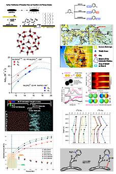
1. A one-dimensional Matlab model, accounting for the different species involved in F-T reactions (CO, H2, C1, C4, C5, C10, C14, C24 and H2O) was built. The model included packings with different porosities and densities. It also included the F-T kinetic by Keyser et al. (2000) for iron catalyst, the Peng-Robinson Equation-of-State for phase equilibria, and the pressure-drop by Eisfeld and Schnitzlein (2001) for fluid flow though packed-beds. Figure 1 shows the effect of packing properties on the pressure drop and CO conversion as a function of the bed length.
2. A computational fluid dynamics (CFD) model was built in ANSYS to provide fundamental understanding of the local hydrodynamics and performance of a MCR. The CFD model was based on a multi-Eulerian approach and includes the pressure drop, F-T kinetics and heat transfer. The CFD model was used to predict the effects of pressure, temperature, inlet gas velocity and H2/CO ratio on the CO and H2 conversions, C5+ selectivity and C5+ yield as shown in Figure 2. The Matlab and CFD models were also used to predict the MCR products as a function of its length (Figure 3).
3. The effect of the gas distribution at the inlet of the MCR and its impact on the flow behavior inside the microchannels was investigated using CFD in the geometry depicted in Figure 4. In the absence of gas distributor (Case 1), the simulations were conducted at superficial gas velocity (UG) of 0.1 and 0.5 m/s; and in the presence of distributor (Case 2), the simulations were conducted at UG of 0.5 m/s. In Case (1), the flow distribution profiles showed (i) high velocities at the center of the reactor and the inlet zone of the channels located in this area, (ii) the formation of vortices at the sides of the high velocity area, and (iii) lower velocities closer to the reactor’s lateral walls as shown in Figure 5. In Case (2), the gas flow was more evenly distributed, thus eliminating the high velocities at the central channels, thereby leading to a homogeneous velocity profile (Figure 6).
Ongoing and Future work:
1. A techno-economic analysis is being conducted using process simulator Aspen HYSYS v7.2 to compare the F-T process in a MCR with the Direct Methane to Methanol (DMTM) process. For each process, the operational performance will be assessed based on the mass and energy requirements, and the economic performance will be evaluated in terms of the net present value (NPV), payback period (PBP) and internal rate of return (IRR). Preliminary techno-economic analysis of the effects of tail gas recycle ratio in the MCR for F-T synthesis on the net energy requirement/capital invested and net energy requirement/kg of hydrocarbon produced are shown in Figure 7.
2. We are currently building a MCR to experimentally measure the hydrodynamic and mass transfer parameters for CO and H2 in a reactor wax under actual F-T conditions. The data will be incorporated into our one-dimensional and CFD models, and used to predict the performance of the MCR for F-T applications, and identify areas of future research. Characterization of the gas-liquid-solid system to be used and stress analysis for the MCR design are also underway.
Education and Outreach:
During the course of this report, we enlisted two undergraduate students, who had the opportunity to learn different modeling techniques, primarily CFD using ANSYS software package and detailed process modeling using Aspen Plus simulator. Two graduate students also worked on the project and earned their MS degrees. Currently, two graduate students are working on the project. Moreover, research results obtained in this project were displayed at a Poster Session by the University of Pittsburgh, aimed at promoting Science and Engineering among underrepresented students.
Figures:
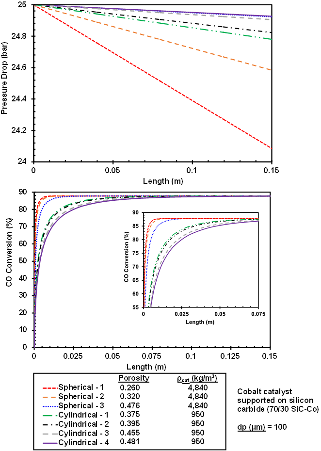
Figure 1: Effect of catalyst packing on the pressure drop (Top) and CO conversion (Bottom)
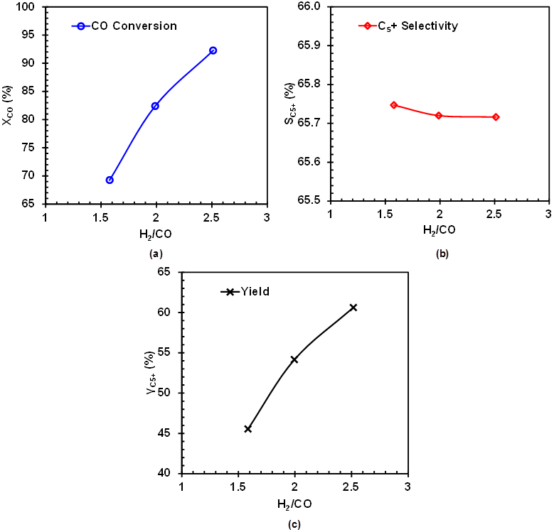
Figure 2: Effect of H2/CO ratio on CO molar conversion (a), C5+ Selectivity (b) and C5+ products yield (c) in a single-channel of the MCR
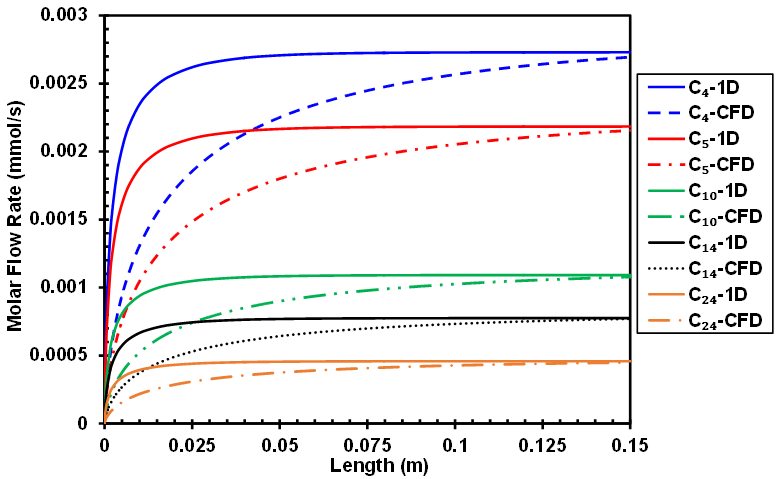
Figure 3: Comparison between the hydrocarbon products flow rates between the 1-D and CFD MCR models predictions

Figure 4: MCR geometry used in the CFD model for gas distribution
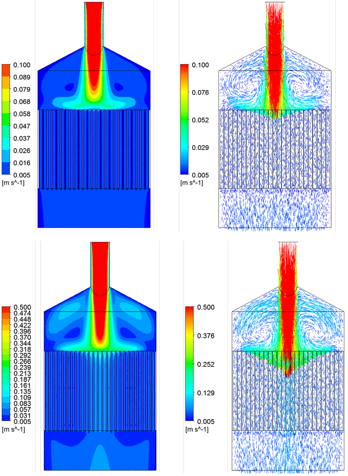
Figure 5: Velocity contours and vectors in the absence of gas distributor UG = 0.1 m/s (Top) and 0.5 m/s (Bottom)
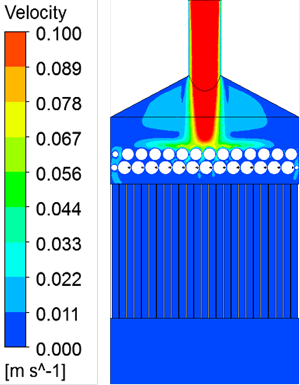
Figure 6: Velocity contours in the presence of gas distributor
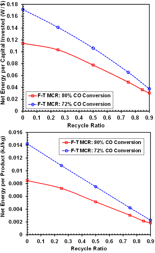
Figure 7: Effect of tail gas recycle ratio in the MCR for F-T synthesis on the Net energy requirement/capital invested (Top) and the Net energy requirement/ kg hydrocarbon produced (Bottom)