Reports: ND953711-ND9: Characterizing Fuel Drop Vaporization at High-Pressure Environments
Song-Charng Kong, PhD, Iowa State University
This project is to conduct fundamental research on characterizing fuel drop vaporization at realistic combustion chamber environments. Last year we have design and fabricated a test chamber, assembled proper optical and data acquisition systems, and conducted preliminary experiments to characterize fuel drop trajectory. This year we further modified the test chamber to sustain high pressures and temperatures, conducted drop vaporization experiments, and developed image processing techniques to characterize drop evolution.
Test chamber modification, fabrication, integration, and testing of a new pressure vessel
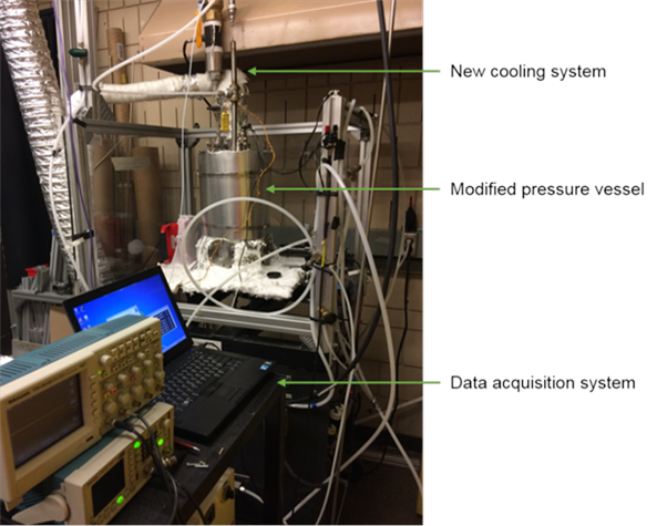
The dimensions were modified to handle high gas pressure and heat the gas inside the vessel at a faster rate. The vessel height was reduced from 18 to 16 inches. The new pressure vessel was tested to withstand a safe gas pressure of 70 bars and the maximum gas pressure of 100 bars. Further, the droplet injection system was redesigned for easier installation inside the pressure vessel. The fuel reservoir, an integral part of this system, was installed outside the vessel, unlike the earlier design, to ensure easier and faster filling of fuel during the experiment. We have completed the integration of the new pressure vessel and modified the droplet injection system with the existing droplet vaporization rig. The integrated droplet vaporization rig with these components is shown in Figure 1.
Experiments, troubleshooting, cooling system design and fabrication
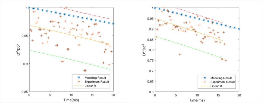
We conducted experiments at 1 bar and temperatures between 27 to 200 oC using low-boiling point, single-component fuels, i.e., n-heptane (BP 98.5 oC) and iso-octane (BP 99 oC). The objective was to evaluate the droplet vaporization characteristics, i.e., reduction of droplet radius with respect to time (D2-t). The droplet radius was measured from the recorded multiple white light images of a steady, consistent, droplet stream at 14 to 15 different vertical locations along the length of this stream. A point gray camera fitted with microscope MX-4 objective recorded these images. At each vertical position, 100 tiff images were captured, resulting in 1400 to 1500 images for a single measurement dataset. The contrast of these images was enhanced using a contrast stretching code developed in Matlab. Droplet edges in these enhanced images were detected using another code based on Canny algorithm. The droplet radius obtained in each image was further processed to show the D2/ Do2 vs. time (ms) results.
During the experiments, we identified the problem with vapor lock in the droplet injection system while conducting high-temperature experiments with n-heptane and iso-octane. The severity of the problem increased for test temperature above 150 oC. A stable droplet stream could not be generated at temperatures above 150 oC. Severe vapor lock and high droplet generator tip temperature were the two major causes of this problem. Therefore, droplet radius measurement was not possible due to the lack of droplet stream images.
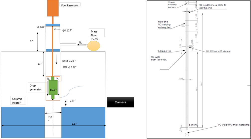
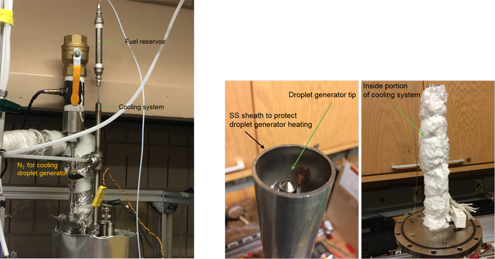
We finalized the design of the cooling system to cool the droplet generator system. The schematic, fabrication drawing, pictures of the system are shown in Figures 2 and 3. The droplet generator cooling system has a 0.5-inch SS 304 tube with a SS plate at the center. The N2 gas, flowing inside the cooling system, cools the fuel line and the droplet generator tip. A proper selection of the N2 flow rate is essential for causing effective cooling. The flow rate is controlled using a mass flowmeter connected to an N2 cylinder.
The fabrication and installation of the new droplet generator cooling system were completed. A vertical gap of 2 inches was maintained between the droplet generator tip and the ceramic heaters. This was done to prevent the overheating of the tip. Graphite insulation was used between the pressure vessel bottom and the base plate. The use of graphite ensured a good seal and lower heat loss to the surrounding atmosphere.
We completed experimental investigation on single component n-heptane at 1 bar and test temperatures 27, 50, 100, 120, 150, 200, 270 oC. The vapor lock problem was not observed up to 300 oC. In the cooling system, nitrogen flow rate was varied from 2 SLPM to 24 SLPM to establish a stable droplet stream. The use of cooling system around the droplet generator has solved the problem of vapor lock.
Post processing and results
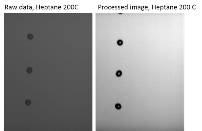
A computer code, developed in Matlab, was used to enhance the contrast of the images recorded at different vertical camera locations. Contrast stretching was done by varying the normalized matrix data in the range of 0 to 1. The code did not affect any pixel value of the image data matrix. The imaging results, including the original and processed images, are shown in the Figure 4.
Another Matlab code was also developed to measure the droplet radius from the multiple recorded images. The code used the Canny algorithm to identify the edge of the droplets. Figure 5 shows detected droplet edges using the Canny algorithm in the droplet vaporization experiments. This code also calculated the average of all the droplet radius measurements at each vertical camera position and revealed D2/ Do2 vs. time (ms) using 95 % confidence interval.
Results at 200 and 270 oC using n-heptane are shown in the Figure 6. Droplet diameters were normalized using the initial droplet diameter. The droplet residence time is based on the frequency used in the experiment for the droplet ejection from the droplet generator tip.
Impact of the research
This research will create knowledge on fuel drop vaporization, which is an important process in a combustion process. Better understanding of the fuel vaporization process can enhance our ability to prepare the combustible mixture and help control the combustion process. This research has allowed the PI to learn the characteristics of drop vaporization at a fundamental level. Drop vaporization is a new research area to the PI. This project also provided the opportunity for the graduate student to design, fabricate, and assemble a system for studying fuel drop vaporization. The graduate student has also conducted preliminary experiments to investigate the drop vaporization phenomena and gained in this area.

