58th Annual Report on Research 2013 Under Sponsorship of the ACS Petroleum Research Fund
Reports: DNI1051511-DNI10: Silicon Quantum Dot Superlattices for High Efficiency Thermoelectrics
Akram Boukai, University of Michigan
Figure 1. (a) A typical planar p-n junction solar cell. Electrons (black dot) at a distance from the junction that is larger than the diffusion length are not collected. (b) A lamellar p-n junction with a smaller collection distance. This geometry increases the probability of carrier collection.
Solar cells are attractive electric power generators since they are a source of clean energy. The most common material used in solar cells is silicon.
- Single-crystal and multi-crystalline silicon accounts for over 90% of the solar cell market.
- That number increases to almost 98% if amorphous silicon cells are counted.
- The primary reason for silicon's dominance of the solar cell industry is its earth abundance and ease of processing. Currently, however, the US receives less than 1% of its electrical power from solar cells.
- The reason is that crystalline silicon solar cell manufacture and installation remains prohibitively expensive. One of the reasons for the high cost of crystalline silicon is the expense required to purify metallurgical-grade silicon (99.9-99.999% pure) to solar-grade silicon (99.999999% pure).
- The purification process accounts for over 40% of the completed cell cost and is required to remove the detrimental metallic impurities found in the raw silicon feedstock.
- If solar cells are to become commercially competitive, the ultimate goal is to achieve a price per watt ratio under $1/W.
- The overall goal of the research was to determine the efficacy of utilizing earth abundant, metallurgical grade feedstock (silicon, magnesium, and iron), for the development of low-cost (less than $1/W) and high efficiency (greater than 15%) solar cells with eutectic composition.
A New Approach: Solar Cells with Eutectic Composition
Figure 3 shows I-V measurements from the literature on a planar β-iron silicide-silicon solar cell.
Here, the single crystal β-iron silicide was deposited onto <111> silicon substrate by molecular beam epitaxy. The crystalline nature of the device is presumably the reason why the current is much larger than the magnesium silicide-silicon device. The planar β-iron silicide-silicon solar cell achieved efficiency values greater than 3% under 1 sun and AM 1.5 illumination. Lamellar silicon-silicide heterojunctions grown via eutectic solidification are expected to achieve efficiencies greater than their planar counterparts.
Crystal Growth of Lamellar Heterojunctions via Eutectic Solidification
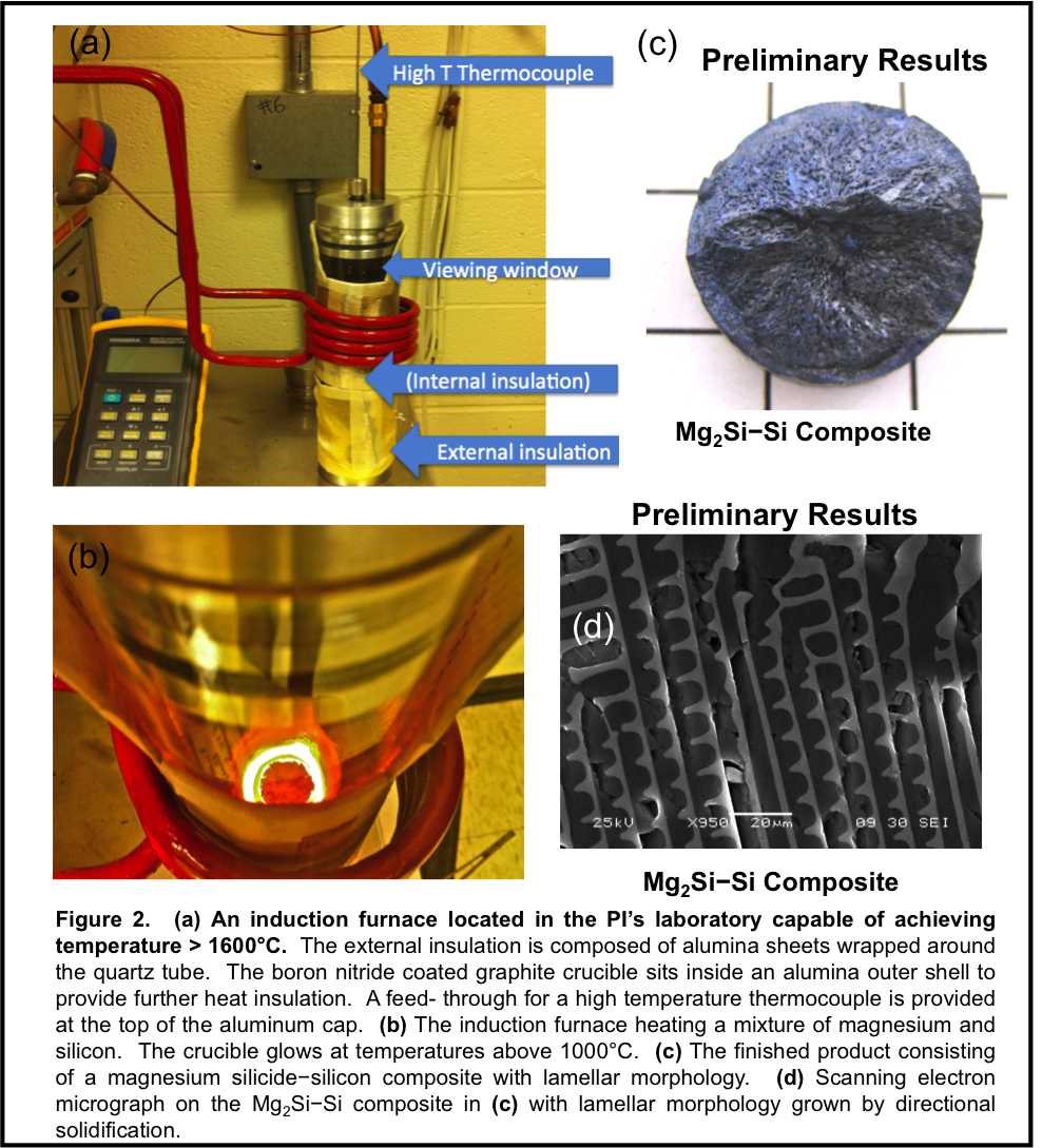
The pellet in Figure 2 was grown by first mixing 44 wt% metallurgical grade magnesium with 56 wt% metallurgical grade silicon in a boron nitride coated graphite crucible. The 1% excess magnesium was necessary because of the low melting point of magnesium, which causes some to evaporate during melting in the induction furnace. The mixture of magnesium and silicon was heated to temperatures > 1000°C for several minutes in the presence of an inert atmosphere of 99% argon and 1% SF6, which completely melts the magnesium and dissolves the silicon. Then, the charge is cooled to room temperature and removed from the crucible. Scanning electron microscopy of the sample shows lamellar domains. Energy dispersive x-ray spectroscopy along with x-ray diffraction measurements confirms the presence of magnesium silicide and silicon domains.
Photovoltaic Efficiency Measurements
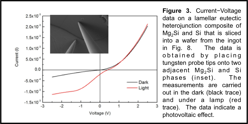
Figure 3. Current-Voltage data on a lamellar eutectic heterojunction composite of Mg2Si and Si that is sliced into a wafer from the ingot in Fig. 8. The data is obtained by placing tungsten probe tips onto two adjacent Mg2Si and Si phases (inset). The measurements are carried out in the dark (black trace) and under a lamp (red trace). The data indicate a photovoltaic effect.
Proof of principle confirmation that the eutectic composite exhibits as a photovoltaic device was obtained by placing two tungsten probe tips onto the top surface of a sliced wafer from the composite. One probe tip is placed onto the Mg2Si phase and the other onto the Si phase. Dark and light measurements indicate a photovoltaic effect, albeit with small short current since the contacts only probe a small section of the entire wafer (Figure 3).
Conclusion
The success of the work will create a new line of research into developing a broad array of materials with eutectic composition for use as efficient solar cells. This will eliminate costly purification steps and ultimately lower the cost of a solar cell below $1/W while maintaining efficiencies above 15%.
Copyright © 2014 American Chemical Society


