Reports: DNI1051341-DNI10: Investigation of a Novel Silicon/Carbon Nanotube 3-D Nanoarchitecture for Binder-Free, Stable Capacity, Lithium-Ion Battery Anodes
 printer friendly
The research goals of work under review are to investigate the structure-property relationships of a novel carbon nanotube (CNT) – silicon composite material for energy and power dense lithium-ion battery anodes with stable cycling behavior. The novel anodes consist of millimeter long, well aligned CNTs, individually coated with a nano-scale thin film of silicon. The studied electrodes contain no binder and reside as a thin sheet material which can be directly integrated into a battery. The unique composite morphology possess five mutually inclusive morphological features hypothesized to be essential for optimum energy and power density as well as cycling performance: 1) very high electrical conductivity, 2) nano-structure and high specific surface area for minimal ion diffusion length, 3) a binder free material, 4) channels for ion diffusion through the thickness of the anode, 5) geometric control of porosity for unconstrained volumetric expansion of lithium-silicon alloy. The research team has made significant progress towards those goals of studying anode structures with those morphological characteristics in year two.
The first years work allowed us to optimize the procedure for depositing silicon on to carbon nanotube array structures with a uniform morphology. The sheer pressing procedure used to densify the arrays was effective (see last years report) but not the best morphology for commercial production of lithium ion battery anodes. Recently the PI has been able to produce aligned carbon nanotube sheets by drawing them from special CNT arrays. These sheets are low density (0.002 g/cm3) and preserve the preferential alignment of the CNTs but they are made into flat fabric like materials that can be easily incorporated into different types of batteries. We produced the flat CNT sheet material and then used it as a scaffold for silicon deposition. Figure 1 shows a schematic of this process. Chemical vapor deposition of silane was again used to coat the CNTs within the sheets. Figure 2 shows the actual process of the CNT sheet winding and the color change after the CVD of silicon onto the CNT surfaces. The fabric-like material remained very flexible and was punched into circular anode pieces for the assembled coin cells.
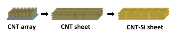
Figure 1. Schematic of CNT-Si sheet structure. Vertical-grown aligned CNT forests drawn into aligned CNT sheets. The self-supported CNT sheet was coated with Si as the main active anode material for the LIBs. A continuous CNT-Si core-sheath structure was obtained.
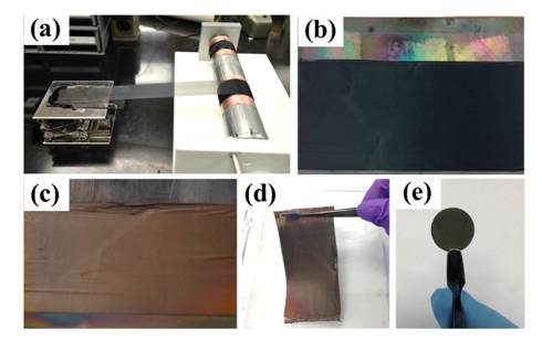
Figure 2. Procedures of synthesizing CNT-Si and CNT-Si-C sheets. a, Wide, continuous aligned CNT sheet was drawn from CNT forests and rolled on a cylinder. b, Photo image of the CNT sheet. CNT sheet was placed onto a quartz plate for CVD silicon coating. c, Photo image of CNT-Si sheet. The color changed from black to brown, indicating successfully Si coating. d, Photo image of CNT-Si sheet. The self-sustained CNT-based structure shows good flexibility. e, Free-standing and binder-free electrode for lithium-ion cell testing.
Figure 3 shows the morphology of the silicon deposited on the CNTs using both scanning electron and transmission electron microscopy. The coatings were very even and uniform across the surface. The overall alignment of the tubes was maintained after deposition. To help reduce effects of the solid electrolyte interface on the performance of the anodes, the same material was also then coated with a layer of disordered carbon using CVD of acetylene on the composite structure. Figure 3d-f shows the effect of the carbon coating on the morphology of the silicon coated CNTs. Both of these types of anodes were assembled into coin cell batteries and the electrochemical cycling properties were examined. The results are shown in Figure 4. Both of the types of samples produced were an improvement on last year's results in terms of specific capacity, columbic efficiency and cycling performance. The samples that did not have the carbon coating had the highest overall specific capacity but they tended to lose capacity after cycling. The silicon coated CNT sheets that had the final carbon layer still showed very high capacity ( four times higher than commercial graphite anodes) and also stable cycling behavior, as shown in Figure 4d. Examination of the anode after the cycling showed a unique morphology. The coated CNTs which were once aligned now had a folded or spring like morphology. It was concluded that the expansion of the silicon on the CNTs put compressive stress on the CNTs causing them to buckle. The alignment of the structure allowed the CNTs to buckle in phase, which has not been observed for any other type of anode structure. This material is very promising and will continue to be studied during the 1-year no cost extension time period. This project has been very important for the PI's career and has had an impact on the student involved as well. Recently this work was published in the high level materials science journal “Advanced Materials”. As a result, the PI has been contacted by multiple people interested in the work and as a result, recently submitted a proposal to NASA to work on a similar topic with a new direction.

Figure 3. Structures of CNT-Si and CNT-Si-C sheets. SEM (a-b) and TEM (c) images of the CNT-Si sheet. SEM (d-e) and TEM (f) images of the CNT-Si-C sheet. Uniform silicon coating was observed on the super-aligned the CNT sheet. Schematic images of CNT-Si and CNT-Si-C structure (g).
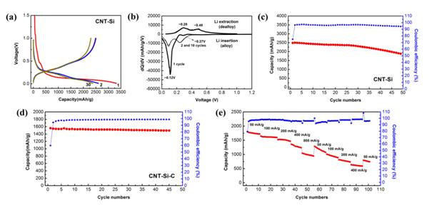
Figure 4. Electrochemical characteristics of CNT-Si and CNT-Si-C sheets. Performance of CNT-Si. Galvanostatic charge-discharge profiles (a), differential capacity curves (b), and cycle performance at 50 mA/g in the potential range of 0.01-1.0 V (c). Performance of CNT-Si-C. Cycle performance at 100 mA/g (d) and rate capability cycled at different current densities (e) in the potential window of 0.01-1.0 V.