AmericanChemicalSociety.com
Reports: AC5 48701-AC5: Nanoparticle Layer-by-Layer Assembly for Fuel Cell Electrodes
Anastasios P. Angelopoulos, University of Cincinnati
Electrochemical investigations were conducted during the second year of the project on Layer-by-Layer (LbL) assembled nanoparticle arrays that were synthesized and characterized using HAADF-STEM and FFT during the first year. These investigations have identified a previously unknown Pt structure synthesized by the PI's group that exhibits substantially enhanced electrocatalytic oxygen reduction reaction (ORR) activity relative to state-of-the-art commercial systems. This new Pt structure exists as an ordered but non-crystallographic assembly of atoms that bridges the transition from atomic clusters to single crystals with lattice structure. Such a novel arrangement of Pt atoms presents a unique opportunity for new research in the fields of electrocatalysis and colloid chemistry that may enable significant improvements in the efficiency of sustainable energy alternatives to fossil fuels.
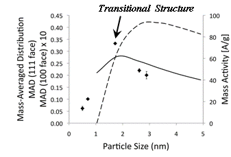
Fig. 1 shows the average ORR mass activity at 900 mV vs. RHE in HClO4 for each particle size in Table 1 obtained from the average of 1, 5, and 10 Layer-by-Layer (LbL) assembled electrodes on glassy carbon. The small standard deviation in this data is a reflection of relatively constant Pt loading per layer obtained using this approach. The dotted and dashed lines in Fig. 1 represent the Mass-Averaged Distribution (MAD) of the (111) and (100) face atoms in truncated, cubo-octahedral nanoparticles for the sizes indicated based on work by Van Hardeveld and Hartog.1 MA for the different particle sizes investigated is compared to the MAD of the atoms in the predominant crystal faces of truncated cubo-octahedral particles as determined by Van Hardeveld for perfectly sized particles. Peak MA for the particle sizes tested is near the peak MAD of the (111) facet. Such a coincidence is consistent with the existing hypothesis regarding the correspondence of ORR structure sensitivity in highly dispersed systems with planar single crystal studies. However, the PI's work indicates that the loss in MA is actually caused by a crystal to cluster transition and the nearly discontinuous peak in activity observed in Fig. 1 correlates to structural re-arrangements associated with the onset of this transition. Peak MA occurs on particles having an amorphous atomic structure not previously observed with Pt.
Table 1: Synthesis Conditions and Particle Characteristics
Figure
1. Average
MA [A/g] plotted versus particle size (diamonds). In the case of larger, crystalline
particles, a relatively smaller loss in MA is observed as the particle size
increases, consistent with the change in the MAD of (111) face atoms for
truncated cubo-octahedral structures. The MA of a
commercial Vulcan-supported Pt catalyst (TKK) was measured under similar
conditions to be 36.7±1.9 A/g at 0.9 V. As may be observed from Fig. 1, the
single-crystals and transitional particles, when incorporated into LbL assembled electrodes, exhibit higher mass activities
than the commercial C-Pt catalyst. The specific activity (SA) of these structures
(based on ECA measurements) was also found to be substantially higher than the
commercial catalyst. An average value of 90.5±7.3 mA/cm2Pt was
obtained for the commercial catalyst, as compared to an average value of 230±21
mA/cm2Pt for LbL-assembled
electrodes of the 2.5 nm crystalline particles. Such activity enhancement with LbL electrocatalyst assembly was hypothesized
in the original proposal for this work. An even higher average SA value of
260±67mA/cm2Pt was measured for LbL-assembled electrodes of the 1.7 nm transitional
particles. The PI has also demonstrated that
similar activity gains are obtained from the transitional particles when they
are assembled via the LbL technique on a Vulcan
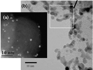
support. Fig. 2(a) is a TEM image of the 1.7 nm transitional Pt
particles synthesized by the PI and supported on Vulcan while Fig. 2 (b) is
that of commercial Vulcan-supported Pt catalyst (TKK)2. The scale of
Figs. 2 (a) and (b) are chosen to be identical. The advantage of the PI's LbL electrode fabrication
technique as regards electrocatalyst monodispersity is evident in these images. Figure 2. (a) Vulcan supported electrocatalyst.
(b) Commercial system from Tanaka A critical aspect of attaining the
activities described in an operating fuel cell is the ability to remove the
stabilizing ligand in electroless
fashion. Methods for accomplishing this have been developed by the PI with this
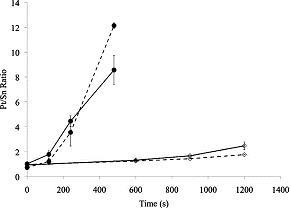
ACS funding and have been recently published. Fig. 3 depicts how NaOH
and HCl may be used to activate the LbL assembled catalyst for this purpose. Figure 3.Pt/Snratio for 10
(dashed) and 20 (solid) layer electrodes assembled ongraphite–epoxy composite
and accelerated with NaOH (filled circles) and HCl (open diamonds).
<>Next Steps. 1.The impact of electrolytic and electroless
activation on the structure of the LbL assembled electrocatalysts (both unsupported and on carbon
support,respectively) that span the crystal to cluster transition will be
characterizedin detail over time to evaluate the durability of the structures
synthesized. 2.Additional funding will be pursued to conduct
electrochemical ad-atominvestigations and structural analyses (SANS and SAXS)
to characterize thesurface chemistry (bond coordination) of the transitional
particles synthesizedand provide more detailed understanding of the fundamental
mechanismsunderlying the ORR reaction. References (1) VanHardeveld,
R.; Hartog, F.Surface Science1969,15, 189. (2) Ferreira,P. J.; la O, G. J.; Shao-Horn,
Y.; Morgan, D.; Makharia, R.; Kocha, S.;Gasteiger, H. A.Journal of theElectrochemical Society2005,152, A2256.

Copyright © American Chemical Society


