Reports: ND1051768-ND10: Super-Adiabatic Combustion in Porous Media with Catalytic Enhancement for Thermoelectric Power Conversion
 printer friendly
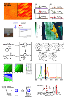
The effects of La-Sr-Fe-Cr-Ru based perovskite catalysts, on matrix stabilized combustion in a porous ceramic media are explored. Highly porous silicon carbide ceramics are used as a porous media for a catalytically enhanced superadiabatic combustion of a lean mixture of methane and air. The direct observation of the flame during the combustion becomes possible due to a specially designed stainless steel chamber incorporating a quartz window where the initiation and propagation of the combustion reaction/flame was directly visible. Perovskite catalytic enhancement of SiC porous matrix with La0.75Sr0.25Fe0.6Cr0.35Ru0.05O3, La0.75Sr0.25Fe0.6Cr0.4O3, La0.75Sr0.25Fe0.95Ru0.05O3, La0.75Sr0.05Cr0.95Ru0.05O3, and LaFe0.95Ru0.05O3 were used to enhance combustion. The flammability limits of the combustion of methane and air were explored using both inert and catalytically enhanced surfaces of the porous ceramic media. By coating the SiC porous media with perovskite catalysts it was possible to lower the minimum stable equivalence ratio and achieve more efficient combustion.
Fig. 1 shows a schematic diagram of the experimental setup used in this work. The combustion chamber is composed of two types of porous media: two alumina honeycomb at each end of the combustion chamber and an articulated SiC or alumina foam in the middle. The images of the cylindrical articulated foam are shown in Fig. 2; the foam is highly porous consisting of 85% of porosity, has a diameter of 20.32 mm, a length of 50.8 mm, and an average pore size of 2-3 mm. The lower porosity (38%) alumina honeycomb ceramic cylinders that are placed at the inlet and at the exhaust of the combustion chamber, between the reticulated foam, has 8 pores per centimeter, a diameter of 20.32 mm, and a length of 25.4 mm. The average pore size of the honeycomb alumina is much lower than the articulated foam’s, which allows the flame to propagate along the axis of the articulated foam ceramic but to quench at top surface of the honeycomb. Therefore, the honey comb ceramic modules acts as a flame arrestor due to their lower average pore size, forcing the combustion zone to be stabilized in articulated ceramic foam section of the burner.
The combustion chamber enclosing the porous burner was composed of stainless steel and featured a quartz transparent window that allowed observation of the flame behavior during ignition. In this study the assembly featured a casing that was insulated on every side with a 25.4 mm thick ceramic fiber board insulation as seen in Fig. 3 (the panel covering the window during combustion experiments is not shown in Fig. 3 to better showcase additional details), to reduce heat loss from the burner, to increase the repeatability of the experiments, and to ensure the measurable effects of the catalysts activity in the chemical reactions of combustion.
Multiple samples of articulated foam ceramics were used in this work. In addition to the uncoated SiC articulated foams, perovskite catalyst La0.75Sr0.25Fe0.6Cr0.35Ru0.05O3, La0.75Sr0.25Fe0.6Cr0.4O3, La0.75Sr0.25Fe0.95Ru0.05O3, La0.75Sr0.05Cr0.95Ru0.05O3, and LaFe0.95Ru0.05O3 coated SiC articulated foams were used inside the porous burner. The catalytically active perovskite coatings were deposited on the surface of the porous media using the dip coating method. Samples of SiC articulated foams were coated with five different compositions of perovskite catalysts. The five perovskite compositions were characterized using Scanning Electron Microscopy(SEM, VEGA II, TESCAN, USA). The dip coating process consisted of forming a suspension of the perovskite powders in isopropyl alcohol and placing the slurry mixture in a test tube submerged in a water bath within an ultrasound machine to ensure stability of the suspension. The articulated foam ceramic was then lowered into the slurry and held suspended for one minute, which allowed enough time for the coating to penetrate the pores and bond to the surface. Once coated the articulated foam was placed in a tray and allowed to dry overnight in the fume hood until all the isopropyl alcohol fully evaporated.
The reactants were allowed to enter the burner from the bottom of the combustion chamber as seen in Fig. 1. The burner was first ignited using a spark near the top of the articulated foam ceramic or at the thermocouple location T7, at Ф = 1.0. Once ignited, the Ф is reduced to 0.7. At an equivalence ratio of 0.7, the flame is very stable given a cold combustion chamber, and the max temperature of the flame does not exceed 1200 oC during warm-up. The fuel flow rate was varied to obtain the desired Ф, and the air volumetric flow rate was held constant at 0.008 m3/min throughout the experiment. A summary of the experiment conditions is shown in Table 1.
The results of these work published in Energy in 2014.
Table 1. Summary of minimum equivalence ratio experimental conditions
Minimum Equivalence Ratio Experimental Conditions |
|
Dry laboratory air volumetric flow rate |
Constant at 0.008 m3/min |
Methane volumetric flow rate |
Progressively reduced starting at stoichiometry |
Steal casing insulation |
25.4 mm of ceramic fiber board |
Porous media in reactor |
Inert or Perovskite coated porous SiC |
SiC articulated foam porosity |
85% |
SiC articulated average pore size |
2-3 mm |
Output |
8 K-type thermocouples |
Input |
Air/Methane flow controllers |
Table 2. Minimum stable equivalence ratio results of multiple experiments of 5 types of perovskite coated and un-coated inert SiC articulated foam.
Coating Composition of SiC Articulated Foam |
Tmax at Ф =0.58, ˚C |
Tmax at Minimum Stable Ф, ˚C |
Minimum Stable Ф |
Number of Runs |
Un-Coated (Inert) |
1030.9 |
994.3 |
0.547±0.018 |
4 |
La0.75Sr0.25Fe0.60Cr0.35Ru0.05O3 |
1158.5 |
1081.4 |
0.525±0.021 |
2 |
La0.75Sr0.25Fe0.60Cr0.40O3 |
989.4 |
1056.2 |
0.525±0.007 |
2 |
La0.75Sr0.25Cr0.95Ru0.05O3 |
953.9 |
1041.5 |
0.535±0.007 |
2 |
LaFe0.95Ru0.05O3 |
1033.7 |
1072.9 |
0.53 |
1 |
La0.75Sr0.25Fe0.95Ru0.05O3 |
906.6 |
1039.2 |
0.51±0.01 |
3 |
Table 3. XRD refinement results
Composition |
a, b, c [Å] |
Volume |
χ2 |
La0.75Sr0.25Fe0.60Cr0.35Ru0.05O3 |
5.548, 5.514, 7.799 |
238.639 |
7.000 |
La0.75Sr0.25Fe0.60Cr0.40O3 |
5.544, 5.508, 7.789 |
237.948 |
4.018 |
** La0.75Sr0.25Cr0.95Ru0.05O3 |
5.496, 5.461, 7.782 |
233.609 |
24.71 |
LaFe0.95Ru0.05O3 |
5.562, 5.569, 7.863 |
243.624 |
4.076 |
La0.75Sr0.25Fe0.95Ru0.05O3 |
5.533, 5.555, 7.853 |
241.421 |
5.676 |
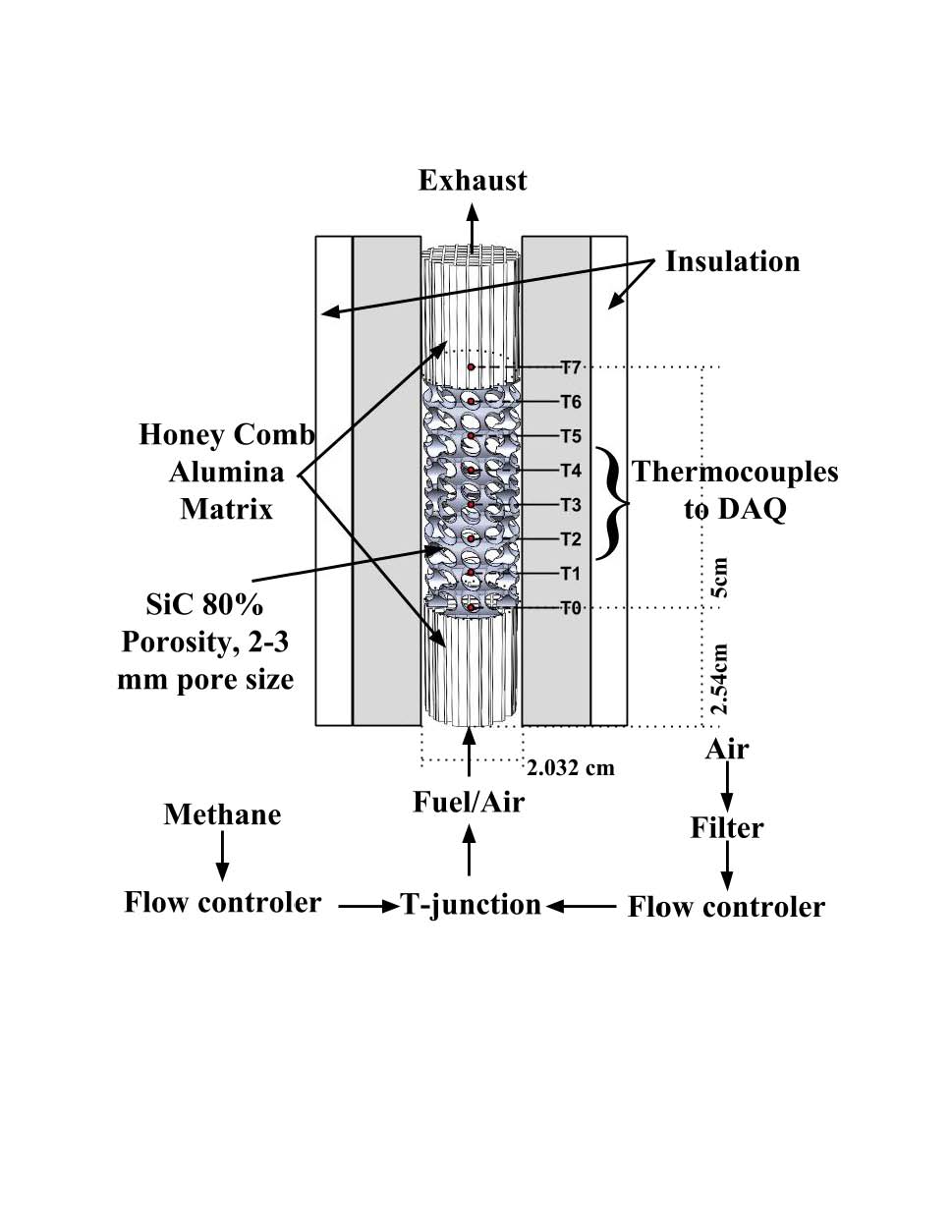
Figure 1. Experimental setup schematic.
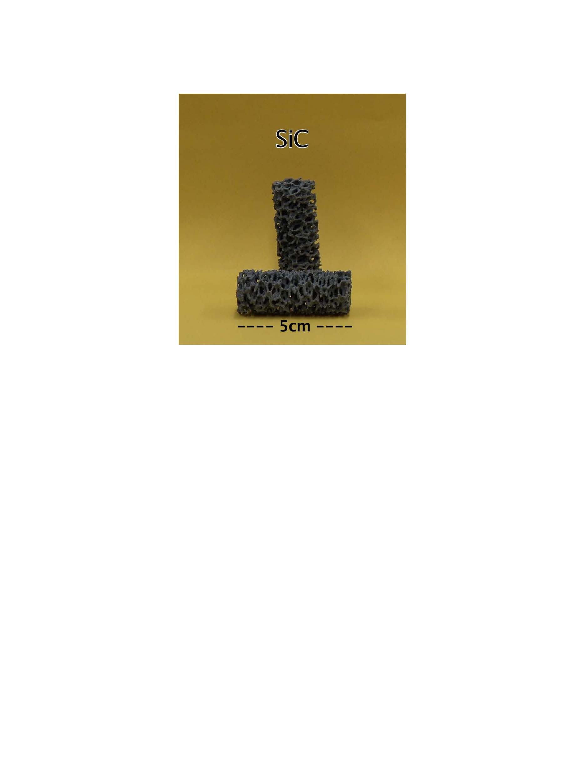
Figure 2. Silicon carbide articulated ceramic foams, used to stabilized the flame inside of the combustion chamber.
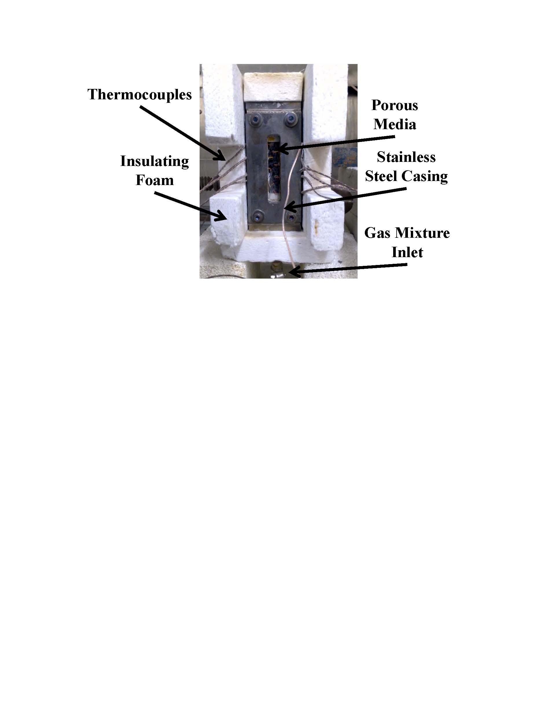
Figure 3. Porous burner, front insulation panel not shown to show additional details.