Reports: ND450709-ND4: Development of N-Aryl-2,3-Naphthalimide Dyes for White-Light Emission with Applications Toward White Organic Light-Emitting (WOLEDs)
Michael D. Heagy, Ph.D., New Mexico Institute of Mining & Technology
The intent of our review [Bao, L.; Heagy, M.D. Current Organic Chemistry, 2014, 18 740-772] was to inform promising researchers of the fundamental requirements for single-emitter chromophore design and present the latest developments obtained through different research directions.
Figure 1. Configurations of the first OLED device (on the left side) and the first WOLED (on the right side)
Our review also demonstrated that the number of single-emitter combinations to obtain white light from OLED devices is ultimately limited by the fabrication process. Hence, a number of design and fabrication issues must be considered as well as the chemical potential of each layer. Nonetheless, as the two main categories of our review (1) small molecule and (2) polymeric systems suggest, no single pathway toward the next flexible screen or low power luminescent device is the key to success.
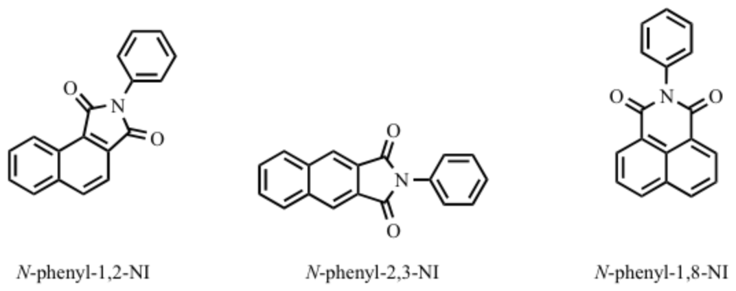
Our second manuscript is currently in preparation and draws entirely on the dissertation work of ACS-PRF supported student Lili Bao. Naphthalimides (NIs) have received considerable attention for both the unique spectroscopic properties and their potential applications in biology in the past few years. NIs belong to a class of chromophores for which spectroscopic and photophysical properties can be changed by: (1) the position of the dicarboximide attached to the naphthalene ring, such as 1,2-NI, 2,3-NI, or 1,8-NI.
Figure 2. Chemical structures of N-phenyl-1,2-, N-phenyl-2,3-, and N-phenyl-1,8-NI
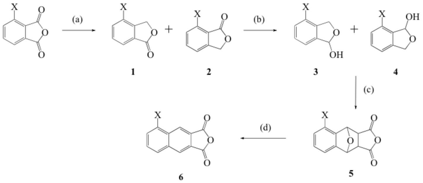
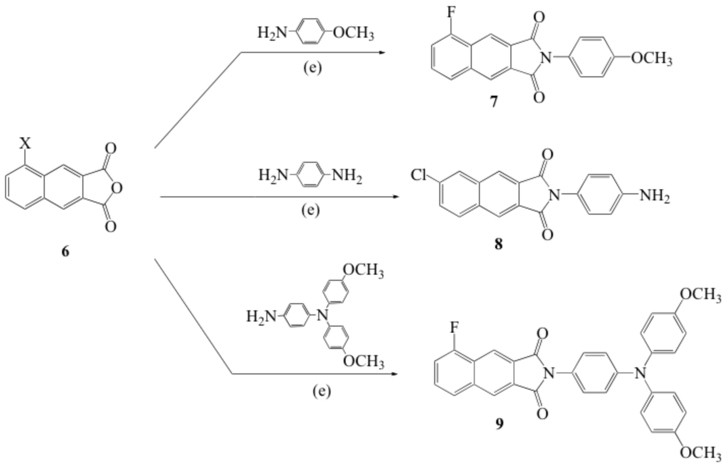
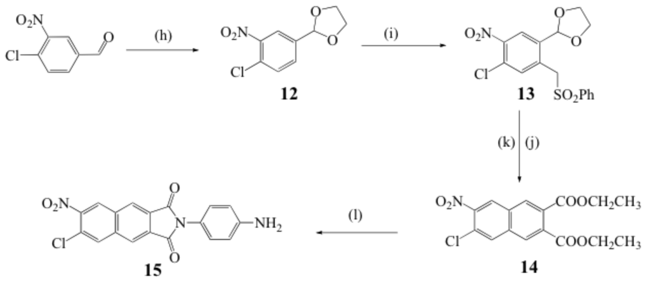
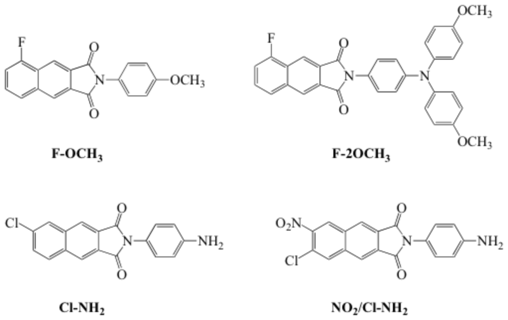
Among NI isomers, N-aryl-2,3-NI exhibited a particular potential for application in white organic light-emitting devices (WOLEDs) because of their high quantum yield, exceptional brightness, small molecular weight ideal for vacuum deposition. To gain greater insights we conducted a detailed study on the photophysical and spectroscopic properties of the N-aryl-2,3-NI derivatives. Scheme 2 to Scheme 5 presents the general procedures for preparation of substituted 2,3-naphthalimides. The compounds investigated in our paper were listed in Scheme 7. We denoted these molecules as F-OCH3, F-2OCH3, Cl-NH2, and NO2/Cl-NH2, respectively.
Scheme 1. Synthesis of fluoro- and chloro- substituted 2,3-naphthalic anhydrides. Reagents and conditions: (a) zinc in acetic acid, reflux, overnight; (b) DIBAL-H, -78 °C, CH2Cl2; (c) maleic anhydride, acetic acid, reflux; (d) concentrated hydrochloric acid in methanol, reflux.
Scheme 2. Synthetic scheme of N-aryl-2,3-naphthtalimides.
Scheme 3. Synthetic procedure for the preparation of 11. Reagents and conditions: (f) Pd(OAc)2, Nat-OBu, P(Ph3)4, toluene, refluxing 6 h; (g) hydrogen gas, Pd on activated charcoal, in methanol.
Scheme 1. Synthesis of disubstituted-2,3-naphthalimide. Reagents and conditions: (h) ethylene glycol, toluene, reflux, overnight; (i) dry DMSO, KOH, ClCH2SO2Ph, overnight, 24 °C; (j) acetic acid/H2O 4:1, reflux 6 h; (k) diethyl maleate, 18-crown-6, K2CO3, CH3CN, reflux, 6 h; (l) p-phenylenediamine, pyridine, reflux, 12 h.
Scheme 2. Chemical structures of N-aryl-2,3-naphthalimides Fluorescence Spectroscopy
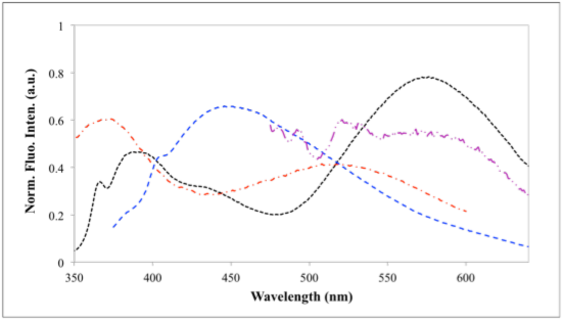
The fluorescence spectra of all the N-aryl-2,3-naphthalimides (F-OCH3, F-2OCH3, Cl-NH2, and NO2/Cl-NH2) are shown in figure 3. All these solutions exhibited broad emissions over 400 ~ 700 nm upon corresponding excitation wavelength. F-OCH3 in ethyl acetate was excited at 310 nm, and it shows dual-fluorescence at SW 370 nm and LW at 520 nm.
Figure 2. The fluorescence spectra of F-OCH3 in EtOAc at lex 310 nm (red dash); F-2OCH3 in cyclohexane at lex 330 nm (black dash); Cl-NH2 in methanol at lex 340 nm (blue dash); and NO2/Cl-NH2 in water at lex 430 nm.
Film Formation.
To investigate the film formation of these compounds, we fabricated 100 nm thickness thin films with the compounds using vapor deposition under ultra-high vacuum. The images of these films were taken with an optical microscope with the magnifications of 40, 100, 200, and 400. The microscopic images with a magnification of 100 were shown in Figure 4.
From the images below, F-OCH3 and F-2OCH3 formed homogeneous films. It was very difficult to deposit Cl-NH2 and NO2/Cl-NH2 using thermal deposition. Cl-NH2 and NO2/Cl-NH2 in the loading boats might decompose because of the high-melting points (> 400 °C) and strong intermolecular interactions (H-bond). Just to make a comparison with a non-homogenous film, image (c) was deposited with 50 nm NPB onto monocrystalline silicon chip.
Figure 3. Optical microscopic images of (a): F-OCH3; (b) F-2OCH3; (c) NPB-50 nm;
Device Engineering.
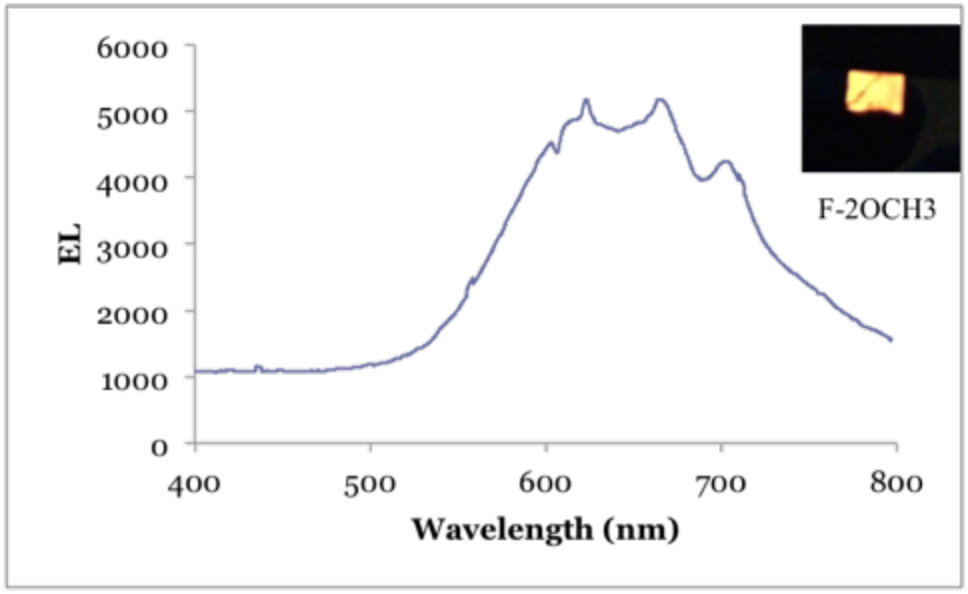
ll the OLEDs fabricated in this part for device tests have the same structure of ITO/NPB (100 nm)/Alq3 (80 nm)/LiF (1 nm)/Al (300 nm). Green electroluminescence was expected from this device under a driving voltage of higher than 4.0 V. The EL of device 2 was shown in the below as well. However, red-emission was observed for device 2. Compared with the solid-state photoluminescence from the previous studies, the SW peak at 400 nm disappeared in the EL spectrum. One possible reason that might account for this is that the SW emission of F-2OCH3 originate from a different but higher orbital energy levels. The estimated energy gap difference between the SW and LW photoluminescence is about 1 eV. Therefore with such a large energy barrier (1 eV) it is difficult to inject electrons and hole to this energy level. For device 1, we were able to observe greenish white light emission.
Figure 4. Electroluminescence spectrum for device 2; photo of the device in operation
The electroluminescent spectra of these devices also showed that dual-fluorescence of the compounds, which we observed in solution, disappeared in solid-state. A plausible explanation appears to be the unlikely probability to inject electrons to the higher LUMO+1 orbitals, therefore the short wavelength fluorescence peak, which we observed in solution, disappeared.


