Reports: DNI1051341-DNI10: Investigation of a Novel Silicon/Carbon Nanotube 3-D Nanoarchitecture for Binder-Free, Stable Capacity, Lithium-Ion Battery Anodes
 printer friendly
The research goals of work under review are to investigate the structure-property relationships of a novel carbon nanotube (CNT) – silicon composite material for energy and power dense lithium-ion battery anodes with stable cycling behavior. The novel anodes consist of millimeter long, well aligned CNTs, individually coated with a nano-scale thin film of silicon. The studied electrodes contain no binder and reside as a thin sheet material which can be directly integrated into a battery. The unique composite morphology possess five mutually inclusive morphological features hypothesized to be essential for optimum energy and power density as well as cycling performance: 1) very high electrical conductivity, 2) nano-structure and high specific surface area for minimal ion diffusion length, 3) a binder free material, 4) channels for ion diffusion through the thickness of the anode, 5) geometric control of porosity for unconstrained volumetric expansion of lithium-silicon alloy. The research team has made significant progress towards those goals of studying anode structures with those morphological characteristics in year one.
One of the first tasks was to deposit silicon conformally onto CNTs within CNT arrays through the decomposition of silane at high temperatures. The student studied nine deposition conditions by varying the temperature and pressure. The objective was to get the most uniform deposition. Higher temperatures and higher pressures led to preferential deposition of the silicon at the surface of the array and was exhibited by a very dark brown or yellow color. Under the optimized conditions the silicon coatings transformed the arrays from a dark black color to a light yellow/brown color as seen in Figures 1 and 2. For our particular chemical vapor deposition system the optimal silicon deposition conditions were: 625oC with 1% silane gas (balance Argon) flowing at 500 sccm at 10 torr. Control of the weight fraction of silicon was determined by the deposition time.
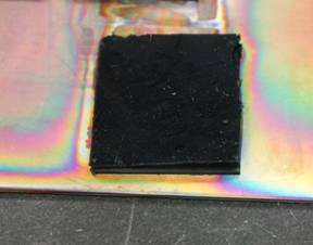
Figure 1. Carbon nanotube array before silicon deposition.

Figure 2. Silicon deposited at the optimized conditions.
To determine the uniformity of deposition of silicon within the array, they were imaged using scanning electron microscopy (SEM). At low and high magnifications the arrays appeared to be very uniform. It was clear that silicon was coating the CNTs and not just nucleating large particles inside of the arrays. To quantify the uniformity of deposition throughout the array, energy dispersive X-ray spectroscopy (EDS) was utilized. Figure 3 shows a SEM image showing the uniformity of a coated array and the locations were EDS was conducted� This technique validated our hypothesis that the silicon would deposit throughout the array, however each sample examined did contain a higher faction of silicon at the tops of the array than the bottoms. However this was expected because, even at low deposition pressure, the gas diffusion length to the bottom of the array is much longer than the top, making deposition at the top more probable.
Figure 3. SEM image of a silicon coated CNT array with locations where EDS was conducted highlighted in yellow.
After the silicon was deposited on the CNT array, the free space in the CNT array was removed utilizing a technique developed in our lab termed "shear pressing". In this process the CNT array is pressed at an angle, providing both vertical and horizontal forces on the array. Vertical alignment of the array is transferred to the horizontal position after the shear pressing. The films could then be directly integrated into the battery anodes without mixing in a binder. The long CNTs used in the process allowed for a high electrical conductivity to be maintained so that we did not have to use a copper current collector in the battery assembly process. Figure 4 shows a schematic of the shear pressing process while Figure 5 shows a silicon coated CNT array after the shear pressing process. The thickness is reduced by approximately 10 times. Thus, a 1 mm CNT array will make a densified sheet of CNT material with a thickness of approximately 100 microns after pressing.
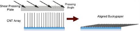
Figure 4. A schematic of the morphology of the CNT array before and after shear pressing.

Figure 4. Shear pressed sheet.
After fabrication into the Li-Ion battery, the performance of the composite structures were compared to baseline samples (Si-free CNT films). Unfortunately the performance of those first structures was only slightly higher than the control samples after a few cycles. After further examining the microstructure of the silicon-CNT anode composites it was found that the silicon was nucleating and growing on the CNTs in nodules. These nodules could easily be separated from the rest of the structure during cycling making them inactive in the charge/discharge process. This was most likely caused by the very smooth surface of our as produced CNTs, which do not provide many nucleation sites for uniform deposition. To solve this problem we deposited a thin coating of amorphous carbon onto the surface of the CNT arrays before silicon deposition. A change in the morphology of the structures is seen in Figures 5 and 6. Figure 5 shows an SEM image of the nodular growth of silicon on pristine CNTs while Figure 6 shows a much more uniform deposition on the CNTs. Both composite structures had approximately 30 wt. % silicon. After a few other optimizations of the deposition process, including a vapor phase etching step to get rid of any residual iron catalyst, the performance of the anode structures became much more in line with the performance expected from their composition and morphology. Figure 7 shows the performance of the anode structure in terms of cycle number vs. specific capacity. Even after 20 cycles the specific capacity of the optimized anodes was close to 1000 mAh/g. This was approximately five times higher than for the baseline CNT anode. Year 2 will include work to more closely understand the factors needed to maintain stable capacity during extended cycling.
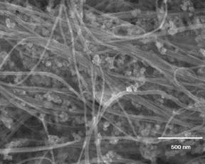
Figure 5. Silicon deposition on pristine CNTs (30% Si).
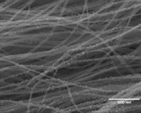
Figure 6. Silicon deposition on amorphous carbon coated CNTs (30%Si).
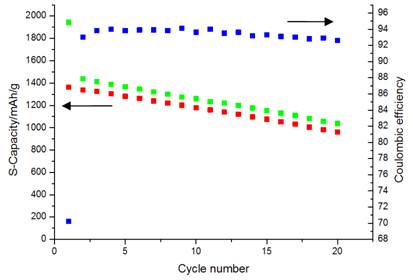
Figure 7. Optimized CNT-Si composite structure with high specific capacity.