57th Annual Report on Research 2012 Under Sponsorship of the ACS Petroleum Research Fund
Reports: B1047343-B10: Design and Synthesis of Novel Pyrene Discotics and Their Investigation in Organic Photovoltaic Cells
Bilal R. Kaafarani, American University of Beirut
PRF Grant Report
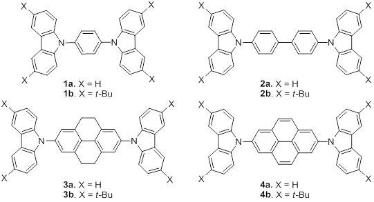
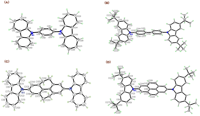
During the fourth year of this project, we determined the optical properties, electrochemistry, and electroluminescence carbazole derivatives 1-4, Figure 1. Single crystals of 1,4-bis(carbazol-9-yl)benzene (1a), 4,4'-bis(3,6-di-tert-butylcarbazol-9-yl)biphenyl (2b), 2,7-bis(carbazol-9-yl)-4,5,9,10-tetrahydropyrene (3a), and 2,7-bis(3,6-di-tert-butylcarbazol-9-yl)pyrene (4b) were obtained from dichloromethane / ethyl acetate and their structures determined using X-ray diffraction. The molecular structures are shown in Figure 2.
Figure 1. Structures of carbazole derivatives.
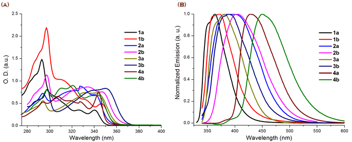
Figure 3a and Figure 3b show the absorption and fluorescence spectra respectively 1-4 in DMF.
Figure 2.ORTEP plots of 1a (A), 2b (B), 3a (C), and 4b (D) with the numbering scheme in projection on the best plane. In the cases of 2b and 3a, where conformational disorder was found, only the major conformation is shown. Thermal ellipsoids are shown with 50% probability level. Hydrogen atoms are drawn as circles of arbitrary small radii for clarity.
Figure 3. Absorption (a) and normalized emission (b) spectra of compounds 1-4 in DMF.
Redox Properties. The solution electrochemistry of 1a-4a and 1b-4b was investigated using cyclic voltammetry (CV) using 0.1 M nBu4NPF6 in dichloromethane as electrolyte. Compounds 1a-4a all undergo irreversible oxidation, consistent with previous reports for other carbazole derivatives without 3,6 substitution, including 2a;1 this irreversibility is attributed to coupling of carbazole radical cations through those positions, in which the spin density is relatively high.2-4 In contrast, 1b-4b all undergo two sequential reversible oxidation processes indicating that these coupling reactions are effectively suppressed.
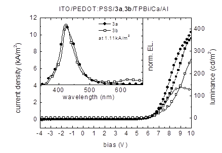
Organic Light-Emitting Devices. To investigate the electroluminescent (EL) properties of compounds 3a, 3b, 4a and 4b OLEDs were fabricated were assembled in a standard sandwich geometry: ITO/ PEDOT:PSS/[carbazole derivative]/TPBi/Ca/Al, 3a and 4a being deposited by evaporation, while 3b and 4b were spin-cast. 1,3,5-Tris(1-phenyl-1H-benzo[d]imidazol-2-yl)benzene (TPBi) is widely used as hole-blocking / electron-transporting material,5 and in the current devices was deposited by evaporation to facilitate electron injection into the active layer. All the devices give deep blue EL, with maxima in the range 422-435 nm, suggesting that emission occurs primarily from the carbazole-material layer; TPBi films show a fluorescence maximum at 383 nm.6
Figure 4 depicts the current density-voltage-luminance (J-V-L) characteristics of devices using 3a and 3b, respectively, as light-emitting layers. The tetrahydropyrene-based OLEDs showed gave maximum luminance values of 138 cd/m2 at 9 V for 3a and 361 cd/m2 at 10.8 V for 3b. Devices using 3a as light-emitting layer show an EL peak maximum at 422 nm and a weak shoulder around 375 nm.
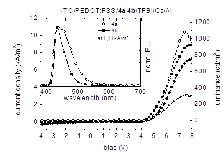
Figure 5 shows the J-V-L characteristics of analogous devices in which 4a and 4b are used as emitters. Maximum luminance values of 1076 cd/m2 were obtained for the 4a device at 7.0 V and 316 cd/m2 at 7.6 V for 4b, respectively. The EL-spectra in the inset of Figure 8 show a broad and slightly structured EL emission peak for compound 4a in the range 410-570 nm with its maximum at 435 nm and a distinct shoulder around 455 nm.
Figure 4. Current density (3a: line with filled circles; 3b: line with filled squares) / luminance (3a: line with open circles; 3b: line with open squares) as a function of the bias voltage of ITO/PEDOT:PSS/3a, 3b/TPBi/Ca/Al devices. Inset: Electroluminescence emission spectra at a current density of 1.11 kA/m2.
Figure 5. Current density (4a: line with filled circles; 4b: line with filled squares) / luminance (4a: line with open circles; 4b: line with open squares) as a function of the bias voltage of ITO/PEDOT:PSS/4a, 4b/TPBi/Ca/Al devices. Inset: Electroluminescence emission spectra at a current density of 1.11 kA/m2.
The device work demonstrates that the tetrahydropyrene and pyrene-bridged compounds are in principle suitable emitting materials for deep-blue OLEDs. While the brightnesses and efficiencies are low compared to state-of-the-art multilayer electrophosphorescent devices employing iridium-based emitters, some of present devices compare reasonably well to blue electrofluorescent devices with comparably simple device architectures, such as devices recently reported based on dendronized or polymerized pyrene derivatives.7-9 It is anticipated that more efficient OLEDs may be obtained by introduction of additional transport layers on the anode side to ensure a more balanced charge injection.10
References
(1) Low, P. J.; Paterson, M. A. J.; Yufit, D. S.; Howard, J. A. K.; Cherryman, J. C.; Tackley, D. R.; Brook, R.; Brown, B. J. Mater. Chem. 2005, 15, 2304.
2) Inzelt, G. J. Solid State Electrochem. 2003, 7, 503.
(3) Ambrose, J. F.; Nelson, R. F. J. Electrochem. Soc. 1968, 115, 1159.
(4) Ambrose, J. F.; Carpenter, L. L.; Nelson, R. F. J. Electrochem. Soc. 1975, 122, 876.
(5) Shirota, Y.; Kageyama, H. Chem. Rev. 2007, 107, 953.
(6) Wang, Z.; Lu, P.; Chen, S.; Gao, Z.; F., S.; Zhang, W.; Xu, Y.; Kwok, H. S.; Ma, Y. J. Mater. Chem. 2011, 21, 5451.
(7) Qin, T.; Wiedemair, W.; Nau, S.; Trattnig, R.; Sax, S.; Winkler, S.; Vollmer, A.; Koch, N.; Baumgarten, M.; List, E. J. W.; Müllen, K. J. Am. Chem. Soc. 2011, 133, 1301.
(8) Trattnig, R.; Figueira-Duarte, T. M.; Lorbach, D.; Wiedemair, W.; Sax, S.; Winkler, S.; Vollmer, A.; Koch, N.; Manca, M.; Loi, M. A.; Baumgarten, M.; List, E. J. W.; Mullen, K. Optics Express 2011, 19, A1281.
(9) Figueira-Duarte, T. M.; Rosso, P. G. D.; Trattnig, R.; Sax, S.; List, E. J. W.; Müllen, K. Adv. Mat. 2010, 22, 990.
(10) Shen, Y.; Hosseini, A. R.; Wong, M. H.; Malliaras, G. G. ChemPhysChem 2004, 5, 16.

