AmericanChemicalSociety.com
Reports: ND10 49638-ND10: Pyroelectrically Mediated Reduction-Oxidation Reactions
Theodore F. Wiesner, PhD, PE, Texas Tech University
Reiteration of Long-Term Goal, Scientific Objective, and Specific Aims
The US Department of Energy (DOE) has called for extensive research into solar-powered catalysts for energy-rich fuels production. The DOE likewise strongly encourages the nation to move toward a hydrogen-based economy, for reasons of sustainability and environmental impact. An extremely important goal in transitioning from a fossil-fueled-economy to a hydrogen economy is the direct splitting of water by visible (i.e. e. solar) light. No environmentally attractive, large-scale, low-cost and high-efficiency hydrogen production process is currently available for commercialization.
Long-Term Goal
Develop a large-scale and efficient hydrogen production process that shifts the paradigm away from thermal, thermochemical, and photocatalytic approaches.
To meet the need for large-scale hydrogen production, we call attention to the fact that the properties of pyroelectric ceramics offer the possibility of mediating solar-driven redox reactions using heat at moderate temperatures as the energy input. Therefore, we propose the following scientific objective and specific aims for a research project.
Prove pyroelectric catalysis can mediate redox reactions.
Specific Aims
1. Synthesize a pyroelectric redox catalyst.
2. Demonstrate pyroelectric water splitting in the laboratory.
Brief Review of the Pyroelectric Effect
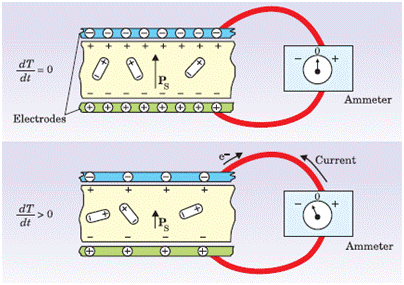
Consider a thin, parallel-sided sample of material (Figure 1), such as a ceramic disk of barium titanate (BaTiO3). The spontaneous polarization, PS, is the electric dipole moment per unit volume. In a pyroelectric material, PS is nonzero at a low reference temperature, Ti. It exists in the absence of an applied electric field, and is equivalent to a layer of bound charge on each flat surface of the sample.
Nearby free charges such as electrons or ions will be attracted to the sample. If a pyroelectric crystal with an intrinsic dipole moment is fashioned into a circuit with electrodes attached on each surface (top panel), an increase in temperature T prompts the spontaneous polarization PS to decrease as the dipole moments, on average, diminish in magnitude. The horizontal tilting of the dipoles, pictured at the bottom, signifies the effect. A current flows to compensate for the change in bound charge that accumulates on the top and bottom of the pyroelectric layer. One can increase the temperature to a level, TH, such that the spontaneous polarization is effectively abolished.
Figure 1. Illustration of the Pyroelectric Effect (adapted from Lang, S. B. (2004). "A 2400 year history of pyroelectricity: from Ancient Greece to exploration of the solar system." British Ceramic Transactions 103(2): 65-70.
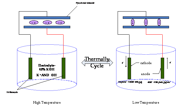
The pyroelectric effect may drive a redox reaction as illustrated in Figure 2.
Figure 2. Thermally Cycling a Pyroelectric Material to Drive Water Electrolysis
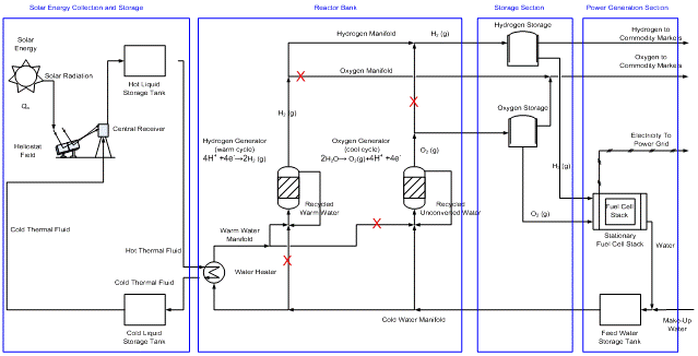
After demonstrating the process depicted in Figure 2, we would ultimately hope to upscale it into the hydrogen process illustrated in Figure 3.
Figure 3. Carbon-Free Power Generation System. Red Xs indicate flow paths blocked for this particular state of the reactor bank
Description of Work on Pyroelectric Redox Reactions
Simple Redox System Driven by Electric Current.
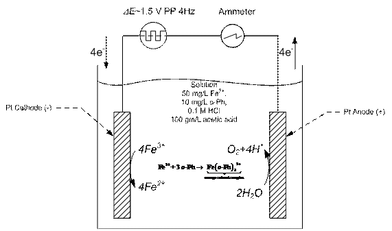
Our initial approach is to demonstrate that a simple redox reaction could be driven by a thermally-cycled pyroelectric material. We have already constructed the apparatus in Figure 4. We chose the familiar reduction of ferric to ferrous iron on platinum electrodes. We tracked the progress of the reaction spectrophotometrically. Ferrous iron forms an orange complex with 1,10 o-phenanthrolene. The anticipated voltage waveform from the cycled pyroelectric was simulated with a Tektronix AFG3021B Arbitrary Function Generator. The simulated waveform was an alternating square wave of magnitude 1.5 V and frequency 4 Hz. The color development was monitored with a GENESYS 6 UV-Vis Scanning Spectrophotometer (Thermo Scientific, Inc.; Waltham, MA) at 510 nm.
Figure 4. Reduction of Ferric Iron Using Alternating Current
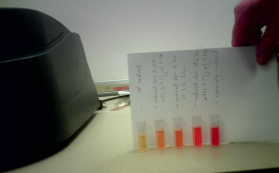
Typical color development for a series of experiments is given in Figure 5.
Figure 5. Color Development for Electrochemical and Chemical Reduction of Ferric Ion in the Apparatus of Figure 4.
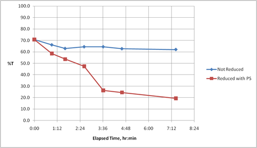
Figure 6. Electrochemical Reduction of Ferric Ion as a Function of Time. Applied Potential 1.5 V and Frequency 4 Hz.
The temporal evolution of the color development is plotted in Figure 6. One can see a drop in the percent transmittance, corresponding to the reduction of Fe3+ to Fe2+ (curve identified as reduced with power supply PS). Compared to the electrochemically reduced solution is the transmittance of a control solution not exposed to the voltage waveform. The transmittance drops only slightly over the same time frame, indicating that the simulated pyroelectric waveform is capable of effecting measurable reduction of the iron.
Simple Redox System Driven by Thermally Cycled Pyroelectric.
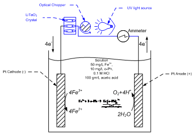
Figure 7. Pyroelectric Reduction of Fe3+. Pyroelectric Drive Illustrated in Blue.
Having established a base case redox system with trackable reaction extent, we are now testing the principle of the pyroelectric drive. We are replacing the voltage source of the apparatus in Figure 4 with a thermally-cycled pyroelectric crystal. The blue portions of Figure 7 depict the modifications. The pyroelectric crystal is a lithium tantalate (LiTaO3) wafer, 3 in diameter by 0.5 mm thick (optical grade, LTOX76005C2 0, MTI, Inc.). This material has one of the highest known pyroelectric coefficients, peff=-230 mC/m2/K. Its spontaneous polarization at room temperature is Pref=60 mC/m2. UV light passing through a rotating optical chopper heats the wafer in a periodic fashion. The slot in the chopper rotates at 4 Hz, inducing an alternating polarization of magnitude 1.6 V and frequency 4 Hz between the faces of the wafer. The band gap of the LiTaO3 does not match the energies of UV light; therefore, the polarization/depolarization cycle is induced by heating, not photoelectrically.
Acknowledgment is made to the Donors of the American Chemical Society Petroleum Research Fund for support of this research.
Copyright © American Chemical Society


