Reports: AC9 48276-AC9: Yield Stress of Complex Fluids: A Numerical Study for a Concentric Cylinder Geometry with Slotted Rotor

Daniel De Kee, Tulane University

We have developed 2-D and 3-D computational fluid dynamics (CFD) models for steady state flow fields in a double concentric cylinder rheometer with a slotted rotor (DCCR/SR).  Using these models, we determined the mechanisms for wall slip reduction and studied the effect of the slot geometry on wall slip reduction.

Fig1.tif

Figure (1):  Geometry of the double concentric cylinder rheometer with and without a slotted rotor

Figure (1) illustrates the geometry in which both a conventional Couette rotor (no slots) and a slotted rotor are displayed.  The slotted rotor design is mainly determined by two parameters: the slot ratio S (defined as the ratio of total area of the slot regions to the rotor side wall area) and the number of slots N.  The constitutive model used in the numerical study of yield stress fluids is a modified Bingham fluid model which was first proposed by Papanastasiou (1987) and later modified by Zhu et al. (2005):

             (1)

The values for the model parameters,  = 0.148 Pa·s, t1 = 0.00294 s, = 9.17 Pa, and m = 2000s; were determined earlier [Zhu et al. (2008)]  by fitting experimental data for a 0.09 wt % Carbopol dispersion to Eq. (1).  The wall-slip boundary conditions are adopted in the simulations by using the "slip-length" method:

                                      (2)

Here vs is the slip velocity (i.e., the relative velocity of the fluid at the wall surface),  and  are the wall shear rate and the wall shear stress,  is the slip length which refers to the beyond the boundary extrapolation of the linear velocity gradient to zero.  The simulation is performed by using commercial CFD software Fluent with the geometry and mesh generated by ICEMCFD.  The governing equations were solved by the pressure-based implicit coupled algorithm. Standard and second-order upwind schemes are used for the spatial discretization of the continuity and momentum equations, respectively.  The gradients are computed via the Green-Gauss node-based method.

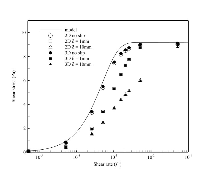
Figure (2) illustrates the differences in the predicted shear stress values between the 2-D and 3-D models for a slotted rotor geometry with slot ratio S = 0.5 and slot number N = 18 as a function of wall slip conditions.  The model (Eq. 1) shows that the shear stress ¦" increases very quickly with strain rate .  Once  reaches a value between 10-3 and 10-2 s-1,  reaches the yield stress  (9.17 Pa) and then increases very slowly.  For the no-slip case, the shear stress obtained with the slotted rotor agrees well with the model curve with only a small deviation near the transition point (around =10-3 s-1).   For a small slip situation (slip length of 1 mm), the curve seems to 'shift' to the right while still keeping an 'S' shape, since a wall slip leads to an overprediction of  the strain rate.  An increase in the slip length to 10 mm shifts the curve further to the right.  The curve also deviates more from the 'S' shape.  However, at large strain rates, say =10-1 s-1, the shear stress is still very close to the yield stress.  The 2-D results agree well with the 3-D results for all wall slip conditions considered, indicating that the 2-D model could be  used to study the flow field for the DCCR/SR design.

Fig2.tif

Figure (2):  Comparison between 2-D and 3-D numerical 
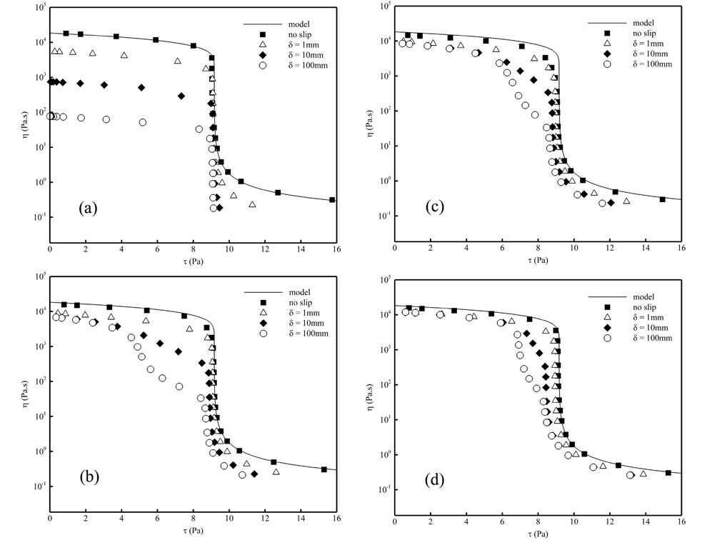
simulation results for different wall slip conditions.

The apparent viscosity of the yield-stress fluid is plotted versus the shear stress for rotors with different S and N in Figure (3). For the non-slotted rotor with no wall slip,  determined at different shear stresses fits the model curve very well [Fig. 3(a)].  This indicates that the conventional Couette rheometer (S = 0) is sufficiently accurate to measure the rheological properties of yield stress fluids.  However, if the rotor wall is characterized by a non-zero slip velocity, the  value obtained with the non-slotted rotor will significantly (and uniformly) shift downward.  For a large slip condition (  = 100 mm), the apparent viscosity differs (drops) by more than two orders of magnitude from the model curve.  Figure 3(b) shows the apparent viscosity predictions based on a slotted rotor with S = 0.5.  As compared with the non-slotted case, the  value slightly drops but it is still in good agreement with the model curve for the no-slip condition.  When slip is considered, the drop in the apparent viscosity is less for the slotted rotor than that for the non-slotted rotor [compare Figs. 3(a) and 3(b)].  When S increases to 0.7 [Fig. 3(c)], the difference in the apparent viscosity between the slip and no-slip conditions is further reduced for the slotted rotor.  Interestingly, an increase in S in the no-slip case seems to cause more deviation in the apparent viscosity than in the case involving slip.  This can be explained by the fact that when S increases, the width of the slot also increases, promoting secondary flow.   The deviation from pure shear flow will then increase.  Figure 7(d) shows better agreement with the model when both S and N are large.  

Fig3.tif

Figure (3):  Prediction of the apparent viscosity as a function of shear stress for different slot ratios and slot numbers, according to the numerical simulation (symbols) and the theoretical model [Eq. (1), solid curve]. (a)  S = 0, N = 0; (b)  S = 0.5, N = 18;  (c)  S = 0.7, N = 18; (d)  S = 0.7, N = 72

These results indicate the best agreement with the model curve is achieved with a non-slotted rotor with the no wall slip, since no secondary flow can occur.  An increase in S under the no-slip (or very small slip) conditions will result in a slight deviation of the apparent viscosity from the model curve.  With an increase in slip length  (or slip velocity), the measured apparent viscosity with the non-slotted rotor drops quickly.  However, adding a large number of slots to the rotor with a large slot ratio significantly reduces this deviation. 

 
Moving Mountains; Dr. Surpless
Desert Sea Fossils; Dr. Olszewski
Lighting Up Metals; Dr. Assefa
Ecological Polymers; Dr. Miller