Back to Table of Contents
46326-AC10
Surface Enhanced Fluorescence in Polymer Semiconductors
Sue Carter, University of California, Santa Cruz
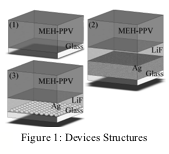
Figure 1: Devices Structures |
 Our
research focused on understanding surface enhanced fluorescence in thin films
of polymer semiconductor poly[2-methoxy-5-(2'-ethylhexyloxy)-p-phenylene
vinylene] (MEH-PPV). Three
different types of device structures were created as shown in Figure 1,
consisting of (1) polymer film alone, (2) with Ag mirror, and (3) with Ag
nanoparticles (NP). For the NP devices, the Ag films were annealed in air using
a four stage anneal process to allow the particles to coalesce from varied
morphologies to a film of spheroids with minimal dispersion of diameters. The
LiF was then deposited by thermal evaporation before a spun cast thin film of
MEH-PPV completed the device structure.
The Ag deposition ranged from 5 nm to 25 nm, the LiF film thickness was
varied from 5 nm to 110 nm, and the thickness of the MEH-PPV was constant at 40
nm. Several data acquisitions were
performed at different sample orientations with several samples to check for
variation and ensure uniformity.
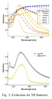
Fig. 2: Extinction for NP diameter. |

Electromagnetic
theory shows that the frequency of the surface plasmon resonance has a
dependence on the diameter, ellipticity, density, and dielectric properties of
the surrounding medium and the NP itself. To
achieve a surface plasmon peak resonance that matches the MEH-PPV peak
absorption (490 nm), Ag deposition was varied from 5 nm to 25 nm in 5 nm
increments. Annealing of the Ag layer resulted in a nanoparticle (NP) layer
that was a uniform dense layer of Ag NPs with resonance peaks varying about the
MEH-PPV absorption peak. Surface
analysis showed the RMS surface roughness to be an accurate estimation of
particle diameter and the average measured width of particles show elliptical
spheroidal characteristics with aspect ratios around 1:7, which is advantageous
for SP excitation.
The
extinction of the Ag layer changes with evaporation thickness and anneal as
shown in Figure 2(a). The blue curves show the extinction of the deposited Ag
layers whereas the orange curves show the extinction of the Ag layers after
formation of the NP layer. Upon annealing the particles making up the Ag layer
become more uniform and the surface plasmon peak tightens. For larger
thicknesses no surface plasmon peak is seen pre-anneal and an approach of the
bulk dielectric properties is observed and a shift toward larger wavelength
resonances is seen after anneal. For a maximum enhancement, the extinction peak
of the Ag NP layer and the peak absorption of MEH-PPV should be matched,as
shown in Fig. Figure 2(b).
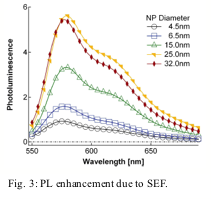
With the introduction of Ag NP in close
proximity of the photoactive polymer, we observe large enhancements in PL. With
a small 5 nm shift in peak PL emission wavelength, the resulting enhancement
above the maximum PL of the control can be larger than a factor of 3 at the
absorption peak of MEH-PPV with out much parameter tuning for optimization
(Figure 4). In contrast, there is an overall reduction in PL for Ag mirrored
devices. This strongly suggests that the SP play a critical role in the PL
enhancement seen in the near-field region.
Fig. 3: PL enhancement due to SEF. |

Figure
3 shows the PL of Ag nanoparticle devices for different Ag evaporation
thicknesses, and a fixed LiF spacer thickness of 20 nm. A general increase in
PL is seen for thicker layers (NP diameters) of Ag with the enhancements much
larger than the mirror control devices.
The peak in PL occurs for a 45 nm LiF thickness which is drastically
different than the surface plasmon enhanced PL in fluorescent dyes such as
rhodamine 6G where the canonical separation distance for dyes is ~4 nm. This
effect can be explained by the differences in the quenching distance dependence
between dyes and polymers. The distance range in which significant quenching in
dyes occurs extends out to 10 nm where
as in polymers the distances range out to 60 nm. So,
for polymers a larger separation distance is needed before maximum enhancement
takes place.
In
summary, our research shows that the PL of MEH-PPV in the presence of Ag NPs is
found to have enhancement for varying NP sizes and varying plasmon- polymer
separation distances. As we would expect within the near field optical range,
the difference in the mirrored and NP devices suggests that the large PL
enhancement is clearly not due to interference effects but may be due to a
superposition of effects including SP electric field enhancement and reflectivity
dependence on change in dielectric constant. Furthermore, we find that, because
polymers are more sensitive to PL quenching than the small molecule systems,
larger separation distances are required to achieve maximum PL enhancement.
Back to top


 Our
research focused on understanding surface enhanced fluorescence in thin films
of polymer semiconductor poly[2-methoxy-5-(2'-ethylhexyloxy)-p-phenylene
vinylene] (MEH-PPV). Three
different types of device structures were created as shown in Figure 1,
consisting of (1) polymer film alone, (2) with Ag mirror, and (3) with Ag
nanoparticles (NP). For the NP devices, the Ag films were annealed in air using
a four stage anneal process to allow the particles to coalesce from varied
morphologies to a film of spheroids with minimal dispersion of diameters. The
LiF was then deposited by thermal evaporation before a spun cast thin film of
MEH-PPV completed the device structure.
The Ag deposition ranged from 5 nm to 25 nm, the LiF film thickness was
varied from 5 nm to 110 nm, and the thickness of the MEH-PPV was constant at 40
nm. Several data acquisitions were
performed at different sample orientations with several samples to check for
variation and ensure uniformity.
