www.acsprf.org
Reports: UR549516-UR5: Determination of Surface Mole Fractions in Mixed Binary AlkaneThiol Self-Assembled Monolayer Films on Gold by Thin-Layer Electrochemical Mass Spectrometry
Introduction. The focus of this research is to examine the feasibility of using electrospray ionization ion trap mass spectrometry (ESI-IT-MS) as a quantitative tool for mixed n-alkanethiol self-assembled monolayers (SAMs). With detection limits in the pmol range, ESI-IT-MS has the sensitivity to be useful for quantitative investigations of SAMs (surface coverages = 7-8 pmol/mm2). Since alkanethiols tend to spontaneously oxidize in solution, our analyses have focused on negative-ion MS of the most stable oxidation product (alkylsulfonates, RSO3-) produced by reaction with H2O2.
These studies will significantly advance the use of ESI-IT-MS as a quantitative tool for SAMs, as our approach should be applicable to SAMs more complex than those investigated here. This work is expanding my analytical capabilities into new areas (quantitative MS, thin-layer flow cell work). Students working on this project are gaining invaluable experience applying an important analytical tool (quantitative MS) to systems of fundamental interest in nanotechnology.
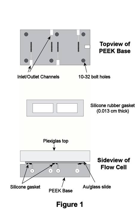
Thin-Layer Flow Cell. As discussed in last year's report, the commercial TLFC employed in our initial studies of oxidative removal of alkanethiol SAMs exhibited poor experimental reproducibility. In response, changes to the TLFC design were made, and a custom TLFC was produced for our work by the same manufacturer (ElectrochemicalALD, LLC). The new design has two thin-layer compartments, each with its own set of inlet/outlet channels so that two experiments can be performed on each SAM-coated Au/glass slide (Figure 1). The two compartments are created by a 0.013-cm-thick silicone gasket that is sandwiched between the slide and PEEK base. Each compartment exposes 3.3-cm2 of the Au/glass substrate to solution, resulting in a thin-layer volume of 40-45 microliters. Laminar solution flow through the compartments is facilitated by a series of 9 holes located at opposite ends of the compartment near the inlet and outlet channels. This redesigned TLFC was received at the end of the first year of the grant.
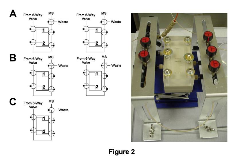
TLFC/Flow Valve System Design. During the second year of this grant, significant time was spent designing and constructing a valve system by which solution flow through the TLFC could be accomplished in a highly reproducible fashion. Initial studies with our latest flow valve design (Figure 2) indicate a significant improvement in experimental reproducibility. In this design, solution flow through each thin-layer compartment (labeled 1 and 2) is controlled by separate T-valves placed at the inlet and outlet. Solution flow into the valve system is controlled by a six-way valve located prior to Compartment 1, whereas solution flow out of the compartments is directed by a fifth T-valve to waste or the MS. Furthermore, connecting the inlet and outlet T-valves in series allows the external solution line to be flushed with blank solvent. Thus, Compartment 1 can be filled while monitoring the MS signal during solution flow (Figure 2A, right). Once filled, the contents of Compartment 1 are isolated from the external solution line by rinsing the external line with solvent to waste (Figure 2C). Afterwards, the contents of Compartment 1 can be flushed to the MS (Figure 2A, right). A similar approach can be employed for isolating and flushing the contents of Compartment 2 (Figures 2B,C).
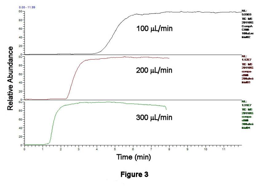
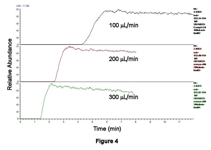
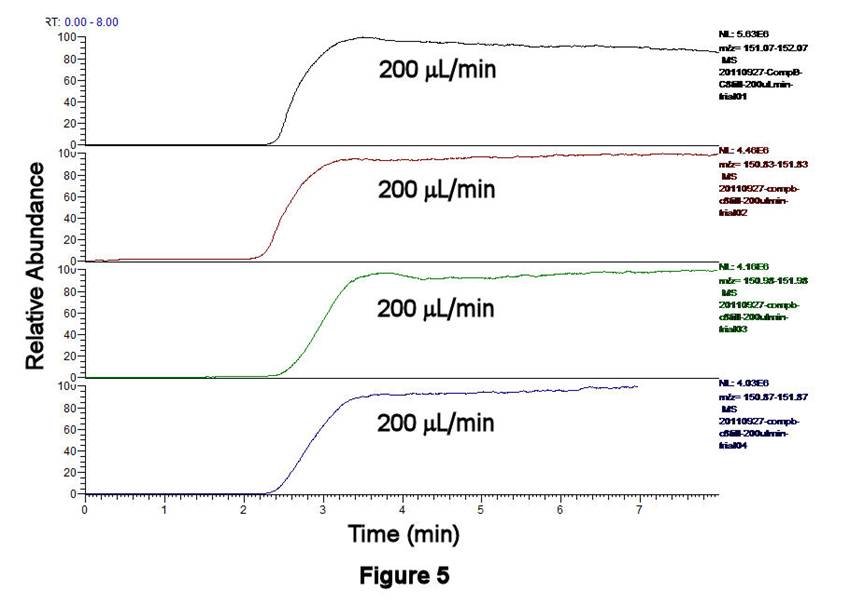
TLFC/Flow Valve System Performance. The performance characteristics of the TLFC/flow valve system have been investigated using ethanolic solutions containing 0.0284 mM octane-1-thiol, 1.19 mM pentane-1-thiol (as an internal standard, IS), and 1 mM ammonium acetate as a buffer; both alkanethiols have been converted to alkylsulfonates by excess H2O2 prior to these experiments. Figures 3,4 display the filling behavior of Compartment 1 as a function of syringe pump flow rate using the above solution. As expected, faster flow rates shorten the filling times and reduce the width of the leading edge of the solution front. This latter effect is important, since longitudinal diffusion can broaden the leading edge of the solution if it is not swept quickly enough. Similar behavior is observed whether one examines the total ion current (TIC, Figure 3) or the C8H17SO3- signal only (m/z 193, Figure 4). Figure 5 displays the results of four successive experiments associated with filling Compartment 2 at a fixed flow rate (200 microliters/min), measured using the IS signal (C5H11SO3-, m/z 151). This high degree of reproducibility for solution filling was obtained for both compartments.
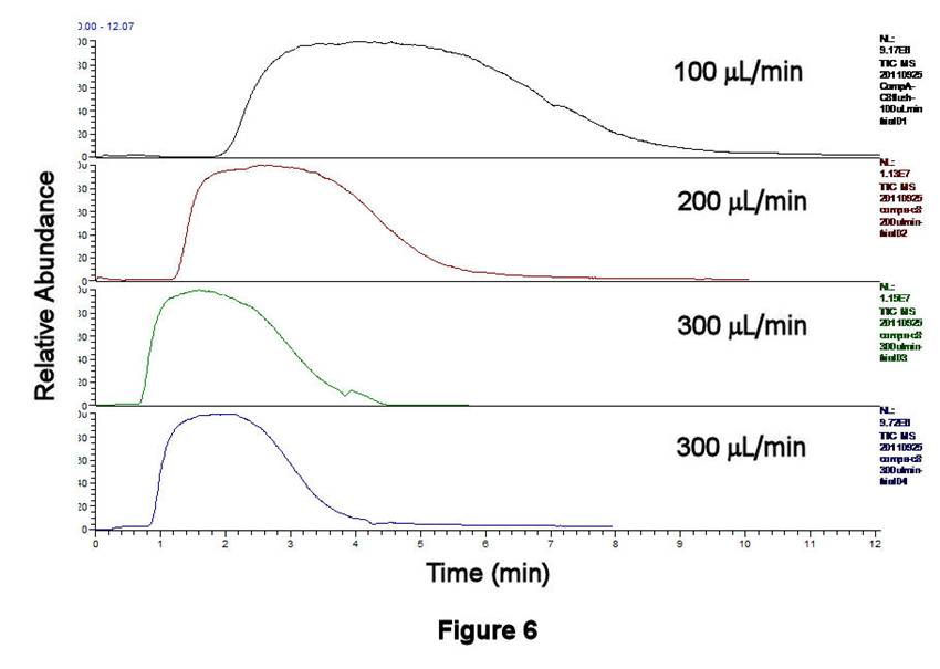
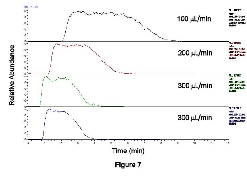
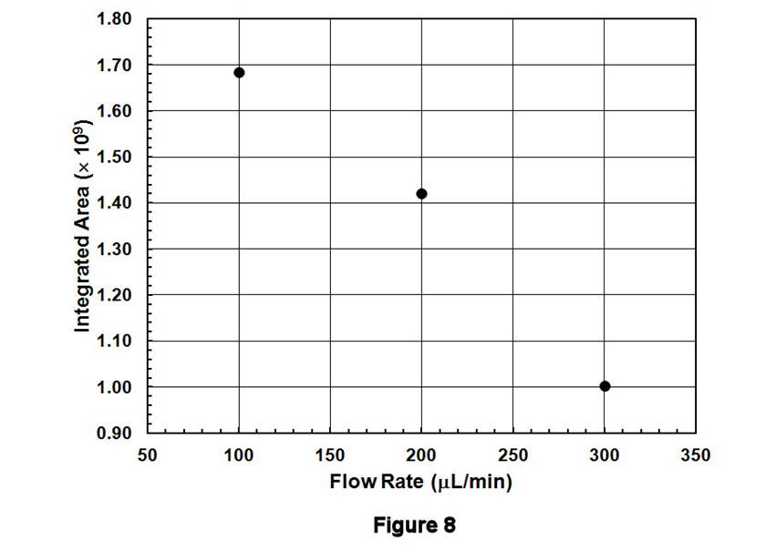
Figures 6-8 display the behavior associated with flushing the contents of Compartment 1 (after being filled with C8H17SO3-/IS solution and rinsing the external line) as a function of flow rate. The peak areas, which correspond to the contents contained between the inlet and outlet T-valves, decrease with increasing flow rate; similar behavior is observed for the TIC (Figure 6), for C8H17SO3- (Figure 7), and for the IS. These data are displayed quantitatively in Figure 8 using the integrated intensities of the IS. Together, these results demonstrate a well-known phenomenon: higher flow rates deliver greater masses to the ESI source, leading to ionization suppression if those masses cannot be reproducibly desolvated, ionized, and extracted into the MS. Thus, an optimal flow rate must be based on balancing the effects of ionization suppression with those of longitudinal diffusion. The former tends to degrade MS signals at large flow rates, whereas the latter leads to long acquisition times and broadened integrated signals at low flow rates. Preliminary results in our lab suggest that flow rates in the 100-200 microliters/min range may be satisfactory for balancing these effects.
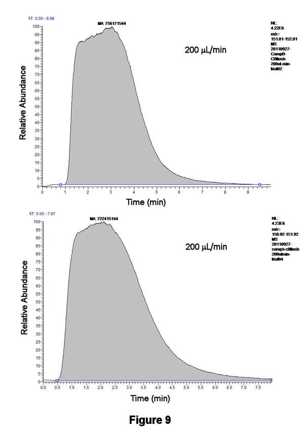
Figure 9 displays the reproducibility associated with flushing the contents of Compartment 2 for two consecutive runs at a flow rate of 200 microliters/min. The integrated areas, which are displayed for the IS, differ by only 4.5%; similar results are obtained with the TIC or the C8H17SO3- signal. These initial results are highly significant since they indicate the high degree of signal reproducibility that can be obtained with our newly designed TLFC/flow valve system.
Future work will focus on generating calibration data with this system in order to precisely determine the compartment volumes, as well as on investigating oxidative stripping experiments with well-characterized SAM films.
|
|
|
|
|
|
|
|
|