www.acsprf.org
Reports: ND1049638-ND10: Pyroelectrically-Mediated Reduction-Oxidation Reactions
Develop a large-scale and efficient solar hydrogen production process that shifts the paradigm away from thermal, thermochemical, and photocatalytic approaches. Progress to Date
As we reported in our first progress report, we adjusted our initial hypothesis to examine steam magnetoelectrolysis (Figure 2), viz.
Steam may be electrolyzed to hydrogen and oxygen via throttling in a magnetic field.
 |
Figure 2. Steam magnetoelectrolysis
In steam magnetoelectrolysis, steam is seeded with sodium hydroxide to provide ionic electrical conductivity. The seeded steam is then passed through a magnetohydrodynamic duct (MHD). In the duct, a magnetic field B generated by a permanent magnet is imposed perpendicular to the gas flow. The resulting current splits water to hydrogen and oxygen. Thus, the steam magnetoelectrolyzer directly converts the enthalpy of the flowing gas (the only energy input to the reactor) to chemical energy in the form of H2. However, extensive calculations indicated that the supersonic steam velocity required so much steam to generate the splitting potential (~1.0 V), that the conversion of the steam to hydrogen would be below 1%. We have abandoned this research track. Findings investigating a new hypothesis
As we were working on approaches to clean production of hydrogen, we realized that we were encountering a more fundamental problem than low efficiency hydrogen production, specifically the intermittency of solar energy. The resultant unsteady state operation leads to poor utilization of equipment and lowered competitiveness with fossil fuel and nuclear energies.
One can store the solar energy in the form of heat in molten salt. Thus, the diurnal fluctuations in insolation to a fuel production facility, such as a water-splitting thermochemical cycle (WSTC), can be smoothed with sufficient salt storage capacity. However, we were not able to find any research investigating the technical and economic aspects of operating a solar reactor with sufficient intermediate energy storage to maintain a steady state.
We propose a solar receiver-reactor with integrated energy collection and storage. The reactor consists of a double-pipe heat exchanger placed at the focal line of a parabolic trough solar concentrator (Figure 3).
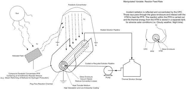
Figure 3. Solar receiver-reactor with integrated energy collection and storage
Molten salt passes through the jacket, absorbing energy from the irradiated outer surface while driving the endothermic oxygen production step of the copper-chlorine water splitting cycle in the reactor bore. Excess hot salt is stored in a thermal storage tank to buffer the reactor from changes in insolation.
We conducted dynamic simulations of the system in Figure 3 as it responds to the solar energy input illustrated in Figure 4.
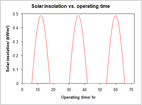
Figure 4. Solar energy input to solar receiver-reactor.
Without circulating heat transfer medium, the conversion and temperature at the reactor outlet vary essentially in phase with the solar energy input, with the average conversion on the order of 10% (Figure 5).
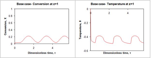
Figure 5. Conversion and temperature at reactor outlet without circulating molten salt.
After addition of the circulating molten salt with storage, we can raise the exit reactor conversion to 100% within 12 hours, and maintain it at that level, along with stabilizing the exit temperature. The attainment of the steady state is depicted in Figure 6. The variables in Figure 6 are dimensionless; the time horizon corresponds to 72 hours, while the temperature ranges from a low of 562 K to 803 K.
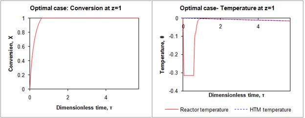
Figure 6. Conversion and temperature at reactor outlet after qualitative optimization
Our simulations indicate that the addition of intermediate storage can sustain steady 100% conversion during 24/7 operation with a reasonable plant layout. The HTM storage for a six MT/day hydrogen plant requires two storage tanks of dimension 15 m high and 90 m in diameter, covering ~1.3 hectares (3.2 acres) of land. The technology employed is extant and mature. There is no need for a fundamental scientific breakthrough to address global climate change. This is important in view of the urgency to reduce dependency upon fossil fuels as primary energy sources.
Impact of the Research on the Career of the Principal Investigator and His Students
The PRF grant has allowed me to make this transition successfully to alternative energy research after fifteen years of conducting research in biomedical engineering. My PRF grant is supporting one doctoral student, Ms. Rong Xu, who is an outstanding researcher with a tremendous work ethic. Four undergraduate research assistants have assisted Ms. Xu for course credit. The experiences the students have obtained through the PRF grant will lead to new scientists and engineers actively seeking alternative energy solutions.
Future Plans Arising from PRF-Supported Research
Our preliminary calculations on the process in Figure 3 are promising. We will expand our analysis to a complete techno-economic analysis of a plant scaled to 500 MT/day of hydrogen. A key question is the scale-up of the directly irradiated, jacketed reactor. A double-pipe exchanger is readily irradiated with a compound parabolic trough, but is limited to low capacities. Can we increase the capacity of the jacketed reactor by combining the reactor tubes in parallel? We envision a shell-and-tube vessel with the molten salt passing shell-side while the outer surface is directly irradiated. We have begun preliminary calculations with four reactor tubes tubes in parallel (Figure 7).
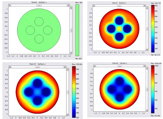
Figure 7. Cross-sectional Temperature Progression in an Irradiated Shell-and Tube Endothermic Reactor from 0 to 20 Minutes. Temperatures in Kelvin.
We hope to expand this model to the typical 1000 tubes seen in industrial shell-and-tube exchangers, while at the same time homogenizing the cross-sectional temperature profile through coupling with a turbulence model. If the computational results remain promising, we will apply for grant funding from the National Energy Technology Laboratory (NETL) of the US DOE to build a working reactor.