www.acsprf.org
Reports: AC948276-AC9: Numerical Simulation of Power Law and Yield Stress Fluid Flow in a Double Concentric Cylinder Rheometer with a Slotted Rotor (DCCR/SR) and Vane Rheometer
Three dimensional steady state flows in a DCCR/SR and a vane rheometer have been numerically simulated. We analyzed and compared the systematic errors in rheological measurements for different test fluids.
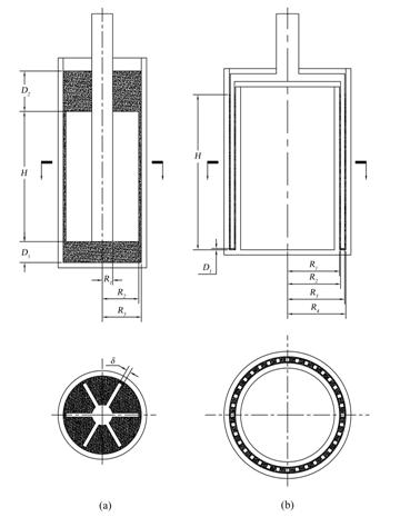
Figure 1: Geometries of (a) the vane rheometer and (b) the DCCR/SR.
Figure (1) illustrates the geometries. There are three factors that are responsible for the deviation of the measured apparent viscosity from its actual value: 1) wall slip effects, 2) end effects, and 3) secondary flow effects. We analyze these separately.
We define the coefficient ¦'slip due to wall slip effects as the ratio of the fluid torque in a rheometer with slip surfaces of the rotor to the torque in a rheometer in the absence of slip:
|
| (1) |
Inaccurate estimation of the correction length leads to end effects-related errors. We define the coefficient ¦'end due to end effects by:
|
| (2) |
Here, H is the rotor length and superscript '*' refers to the correction length used. We define the coefficient ¦'2nd due to secondary flow effects as the ratio between the measured and true values of the fluid apparent viscosity (no slip) and ¦'end equals one:
|
| (3) |
Here superscript '*' refers to the measured value of the apparent viscosity. The total error due to these effects is:
| | (4) |
The constitutive model used in the numerical study of yield stress fluids is a modified Bingham model:
|
| (5) |
where ¦" is the extra-stress tensor,
![]()
![]()
Figure 2: Accuracy coefficients due to (a) wall slip effects (b) end effects and (c) secondary flow effects of a vane rheometer (solid bars) and DCCR/SR (open bars) for power law fluids with different n indices.
Figure (2) compares the three accuracy coefficients between the two designs for power law fluids. In Figure (2a), with free slip ¦'slip for both designs less than unity, indicates an underprediction of the rotor torque. Even for n = 0.01, the torque measured with a vane rheometer is only 87.2 % of the corresponding value under no slip conditions. The ¦'slip further decreases for a vane rheometer with an increase in n, reaching a minimum of 68.8 % for a Newtonian fluid (n = 1). With 60 % slot area ratio, the ¦'slip of the DCCR/SR is smaller than that of a vane rheometer but less dependent on n (~ 60%). In Figure (2b), a vane rheometer has a much larger error due to end effects (¦'end ¨C 1) than the DCCR/SR. This result can be explained by the small thickness of the slotted rotor, leading to a small area of the end surfaces in the DCCR/SR. For a vane rheometer, the accuracy coefficient due to end effects varies significantly with n. For Newtonian fluids, the error due to end effects is -10% for the measurements with a vane rheometer. This error can be eliminated only with the calibration of the correction length. For the DCCR/SR design, ¦'end is ~ 1 and is independent of n. Thus, there is no need for the recalibration of the device. In Figure (2c), the apparent viscosity measured with a vane rheometer or DCCR/SR will deviate from the true value due to secondary flow effects even if all end effects are removed. For a Newtonian fluid, the experimental data as well as our numerical results, show that a vane rheometer predicts only 60% of the true apparent viscosity value. However, the DCCR/SR consistently shows less secondary flow effects than a vane rheometer. For Newtonian fluids, it is possible to reach about 87.3 % of the true value with the DCCR/SR, while a vane rheometer gives about 60.3 %.

Figure 3: Comparison of the total systematic error in apparent viscosity measurement between a vane rheometer (squares) and a DCCR/SR (circles and triangles) for (a) power-law fluids and (b) a yield stress fluid. Negative values indicate the underprediction of the apparent viscosity.
The total error with the two designs is plotted in Figure (3) for no slip (closed symbols) and free slip conditions. For power law fluids (Figure 3a), the error generated by a vane rheometer is more dependent on the power law index n. This variation is much smaller for a DCCR/SR. When there are no wall slip effects, the DCCR/SR will have higher accuracy than a vane rheometer for any power law fluid. Under free slip conditions, the DCCR/SR still has higher accuracy than a vane rheometer when the power law index n > 0.5. For a yield stress fluid, (no slip conditions), a vane rheometer will have ~ 46% underprediction error in the low shear stress region; the DCCR/SR with 60 % slot area ratio has only 10 % underprediction. In the case of free slip, the DCCR/SR design with 90 % slot area ratio will be more accurate than a vane rheometer for the whole range of shear rates.
Our results indicate that: (1) a DCCR/SR is able to accurately measure rheological properties of a wider spectrum of test fluids than a vane rheometer due to significant reductions of end and secondary flow effects; (2) the rheometer design can be optimized by analyzing the accuracy coefficients separately which allows us to determine the dominant source of the measurement error and then to provide a solution for reduction/elimination of this source.
Impact statement: in this research we explore a variety of aspects of determining the yield stress of complex fluids, via numerical analysis. The project involves a Ph.D. student who is also being trained in CFD (Fluent) and a postdoctoral fellow who recently obtained an industrial position with Schlumberger.