Reports: B9
47193-B9 Simulation and Experimental Investigation of Energy Losses in Dividing Flow
Background
This grant is focused on providing energy loss coefficients, K values, for fluid flow laminar flow in arbitrary junctions as in Fig. 1. These junctions may be present in naturally occuring porous media and in many recent microfluidic devices. These loss coefficients could be used in microscale modeling of porous media in reservoirs, aquifers, or any where laminar branching flow may be considered. One additional aspect of these coefficients is that they could be used to make calculations in non-Darcy (inertia dominated) flows in porous media. Non-Darcy flows are not nearly as well understood as Darcy models of porous flow.
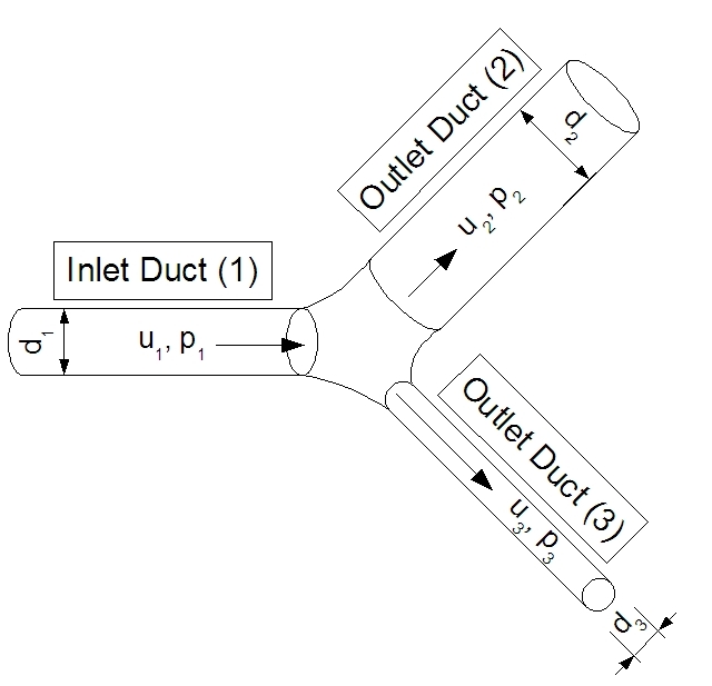
Figure 1: Dividing Flow Junction
Overall
Progress
In the past year the team at UCO, consisting of three undergraduate students, one graduate student (during Summer 2009 only), and the PI, have made significant strides in realizing the project's goals. Our ability to automate our computational fluid dynamic simulations has improved dramatically along with the refinement of several home grown computer codes and the computational meshing technique. Our experimental system has also evolved significantly in the last year; to the point that we can make repeatable measurements of small pressure differences (±5 Pa) and of flow rates as low as 13 ml/min.
As a result of our progress we are now able to use our simulation software and home grown codes to simulate on the computer exactly the conditions that are ongoing in an experiment. We are currently using this technique to validate our earlier and recent simulation results. In July 2009 we were able to confirm that our measurements of loss coefficient for a particular junction matched the simulated junction within 1%. Since that time we have been preparing and have started carrying out additional measurements to perform more comparisons with our simulation results.
Computational Progress
In our simulations of flow in junctions we are now able to pick almost any angles and inlet and exit diameters, and be able to have our computer codes generate a three-dimensional planar geometry of the junction. Improvements in this area were carried out by Tim Handy, an undergraduate working on the project. Our simulation process is controlled by a single computer code. This code allows us to specify a set of Reynolds numbers, diameters, and flow fractions, which will create all necessary files for the set of simulations we want. This code makes possible the following steps:
-
A code we have written in Microsoft (MS) Visual Basic for Applications (VBA) works with SolidWorks, three dimensional modeling software, to produce a two dimensional outline of a junction for specified angles and diameters. This code then creates a sold model of the junction that is written out to a standard graphics format. A sample junction geometry is shown in Figure 2.
-
The junction model is read into meshing software, GAMBIT, that adds inlet and exit tubes and meshes the entire model. An example of a meshed model is shown in Fig. 3.
-
The meshed model is read into FLUENT, computational fluid dynamics software, along with simulation parameters and flow in a junction is simulated. We have this set up so the simulation may be performed on either a personal computer or a computer cluster owned by the UCO Engineering and Physics Department.
-
After all simulations in the chosen set have run, our main code may be used to determine energy loss coefficients for all simulations. A sample of simulation results is shown in Fig. 4.
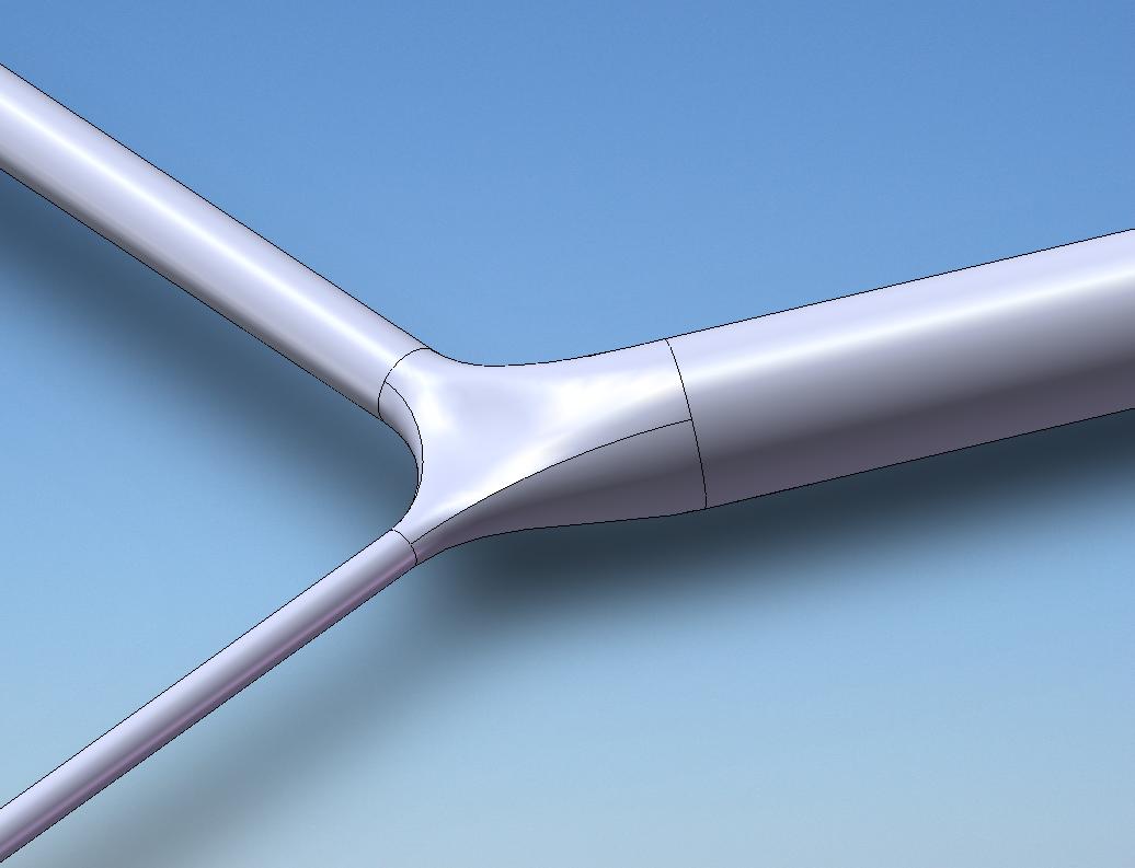
Figure 2: Solid model of arbitrary junction.
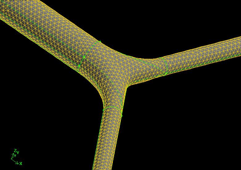
Figure 3: Meshed model of arbitrary junction.
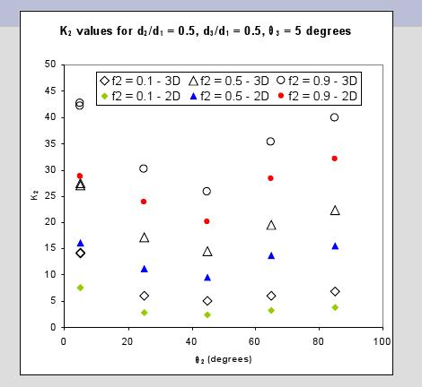
Figure 4: Loss Coefficient Results comparing 2D and 3D simulations.
We are
currently extending our junction simulations for which we have
published results, all at a Reynolds number of 15, to Reynolds
numbers ranging to 1500, to ensure we are approaching published loss
coefficients for common geometries such as "tees" for turbulent
flow.
As part of ensuring our meshing techniques were effective we were able to complete two studies that have technical significance for microflows in general. One of these studies was to develop laminar loss coefficients for microelbows to validate our junction meshing technique. The other study involved ensuring the tubes leading to the junction were long enough to give fully developed flow entering the junction and the associated meshing technique for the entrance and exit tubes for the junctions. Each of these studies resulted in papers presented at the Summer 2009 Fluids Engineering Conference.
Our simulation goals for the coming year include junction simulations focusing on a small number of geometries with a variation in Reynolds number from 10 to 2000, and to begin simulations of non-planar junctions.
Experimental Progress
Our experimental system has improved mechanically in how it functions and electronically in terms of improvements in our measurements -- the current system is pictured in Fig. 5. Mechanical improvements have been spearheaded by Willy Duffle. These improvements include: a new technique to mill acrylic test sections and produce gaskets that ensure leak-proof operation (shown in Fig. 6), custom milling of brass fittings, for connections to system tanks, and a modular system that makes switching test sections, flow straighteners, and pressure measurement ports very easy.
Electronic improvements have been taken on by Jesse Haubrich, an undergraduate working on the project. These improvements include a custom-made printed circuit board (shown in Fig. 7) designed for our system to minimize noise and allow our small pressure difference measurements, custom computer codes to control our data acquisition system, and to capture and display incoming data in convenient ways. We now have two new students (sponsored through other grants) using this system to help us capture data for specified Reynolds numbers, flow fractions, and geometries.
Our immediate experimental goals are to continue experiments for comparison to our simulation results and any published results. We also would like to produce and test actual microscale junctions as well as non-planar junctions.
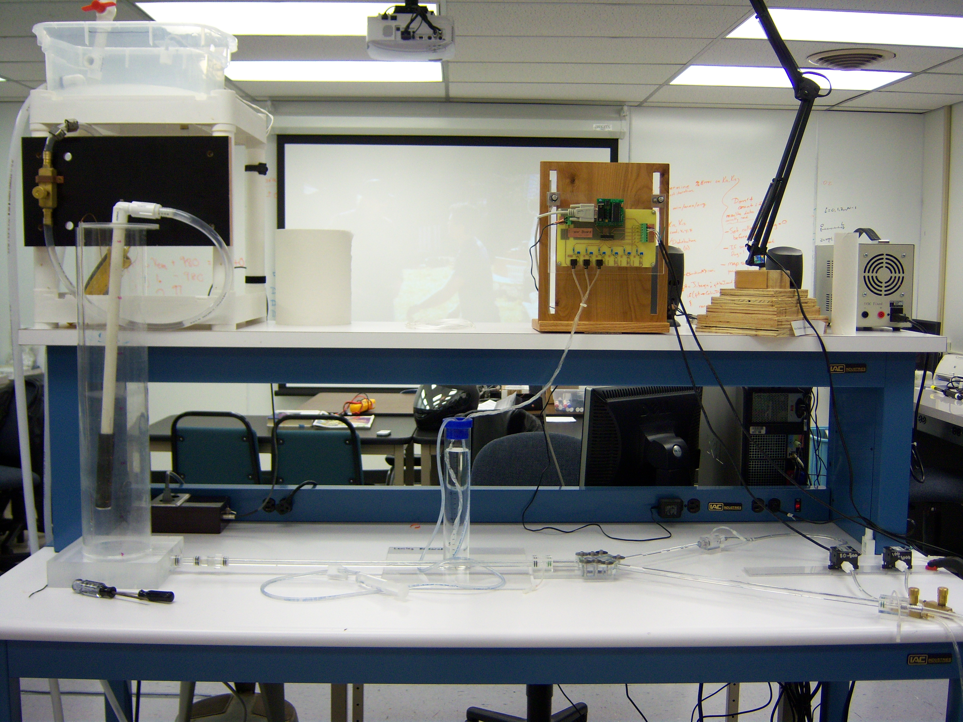
Figure 5: Current Experimental System.
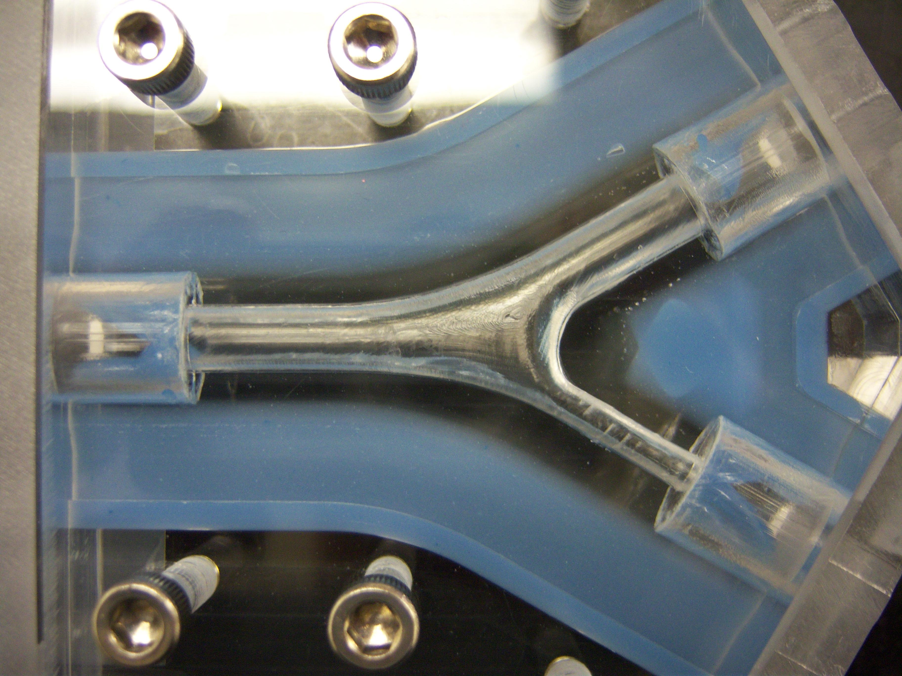
Figure 6: Milled acrylic Junction. The inlet tube (on the left) diameter is 6.35 mm.
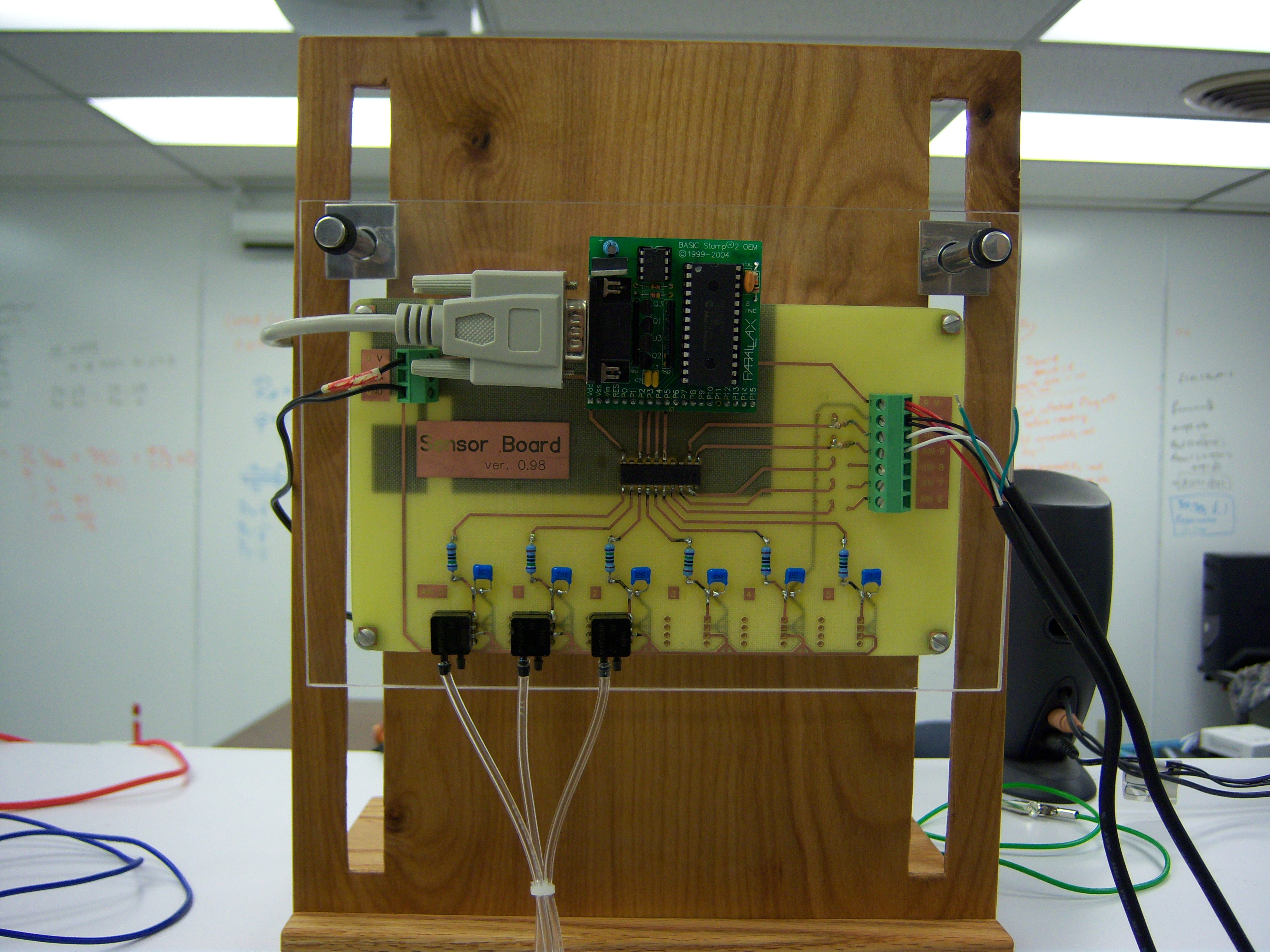
Figure 7: New printed circuit board to measure pressure differences and flow rates.