
ACS PRF | ACS
All e-Annual Reports

42939-AC9
Experiments on Drop Coalescence in Liquid/Liquid Systems
Previously, we investigated the drop coalescence mechanism for head-on collisions. The drops must collide with sufficient inertia such that they deform significantly increasing the velocity magnitude streaming toward the dividing interface. If the large velocities in the streaming flow reach the center plane, then they can induce a strong outflow in the thin film between the drops. The objective of the current study is to understand the dynamic behavior of colliding drops and the mechanism behind coalescence in flows with varying Weber number and collision angle. Pairs of water/glycerin drops were injected into silicone oil and traveled on downward trajectories before colliding. Simultaneous dual-field PIV measurements were obtained to characterize coalescence and rebounding behavior for Weber numbers (We) of 1-50 and collision angles (q) of 20-45 degrees below the horizontal. Dual-field measurements gave an insight into drop trajectory and small-scale behavior within drops as the Weber number and collision angle were varied independently. The results indicated that, for the pair of fluids examined, a fixed Weber number (We = 11) separated rebounding from coalescing cases. This value of Weber number remained constant over the range of collision angles tested. Two cases with different We but same collision angle are presented in Fig. 1. In the coalescing case, the thin film ruptures in the lower portion where the local downflow is strong (see red dot on Fig. 1(a)). In the rebounding case, the vortex ring structure is tilted downward and is more skewed than the corresponding structure in the coalescing case. In the coalescing case, each ring is tilted more inward so that the downstream core sections are focused closer to the center plane and thin film. The vortex pair and the previously deforming interface on the outside of each drop in the higher inertia case induce a stronger inflow as well as a stronger local downflow that is maximized at the center plane as shown in Fig. 1(b). The downflow acts to thin the film between the drops eventually causing the film to rupture in this region. Our previous report mentioned that strong drop deformation combined with vortex interaction yields the appropriate conditions for thin film rupture, and drop coalescence. Not only is the drainage velocity higher in the coalescing case, but also the available time for drainage is longer.
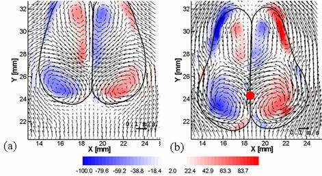
Figure 1: Sample vector fields at the time of maximum film length, (a) Rebounding: We = 11, q = 34°Ć, t* = 0.94, and at the time of film rupture, (b) Coalescence: We = 22, q = 34°Ć, t* = 1.77. Vectors show velocity [m/s] relative to the drop falling velocity. Colors show vorticity [1/s]. Red is counterclockwise rotation and blue is clockwise rotation.
Two cases with different collision angle but same We are presented in Fig. 2. The drop shapes for the shallow collision angle are close to symmetric about the horizontal while the shapes for the steeper collision angle are broader toward the bottom. In these plots, we can see that the different shapes correspond with different vorticity distributions. The paired ring cores near the bottoms of the drops for q = 40°Ć appear stronger and are focused further from the interface than for q = 17°Ć. The resulting ring structure is tilted more downward for q = 40°Ć with the solid lines in Fig. 13 showing the angle of each ring. In Fig. 2, the red dots show the location of film rupture for each collision angle. The film rupture location moves upward as the collision angle increases. For each case examined, the film rupture location occurs slightly downstream of the location of maximum downward velocity in the thin film.
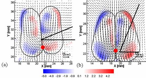
Figure 2: Sample vector fields at the time of rupture: (a) Coalescence: We = 16, q = 17°Ć, t* = 1.43, (b) Coalescence: We = 16, q = 40°Ć, t* = 1.35. Vectors show normalized velocity. Colors show normalized vorticity. Red is counterclockwise rotation and blue is clockwise rotation.
Our work provides new understanding of when and how drops coalesce, where in the past year, we were able to isolate the effects of two independent parameters. The results provide unique data for numerical modelers seeking to validate codes with coalescing interfaces. In the long term, these codes are needed to accurately predict coalescence behavior related to transport, mixing and separation of petroleum products in both industrial and environmental applications.