
ACS PRF | ACS
All e-Annual Reports

42935-AC9
Nanotribology of Ultrathin Confined Liquid Films
During this second year period (9/1/2006 - 8/31/2007), our research focus has been placed on the understanding of the origin of the repulsive hydration force between two mica surfaces immersed in water. This is motivated by the early observations by Israelachvili and Pashley in 1980s in surface force apparatus (SFA) measurement [Israelachvili, J. N. & Pashley, R. M. “Molecular Layering of Water at Surfaces and Origin of Repulsive Hydration Forces.” Nature 306, 249-250 (1983)], and recently, by the surface force balance (SFB) work by Raviv and Klein [“Fluidity of bound hydration layers.” Science , 1540-1543 (2002)]. This research shift is also motivated by one of our first-year findings, the formation of the so-called “bilayer ice” [Leng, Y. S. & Cummings, P. T. Hydration structure of water confined between mica surfaces. Journal of Chemical Physics 124, 74711 (2006)]. In that study, since we used a conventional NVT canonical ensemble in molecular dynamics (MD) simulations, we were unable to determine the capability of hydration layers to support the normal loads. In other words, the “squeeze-out dynamics” is missing in that study. This has led to a fundamental question that needs to be answered: how easy or difficult, or at what loading level will we be able to obtain the bilayer ice?
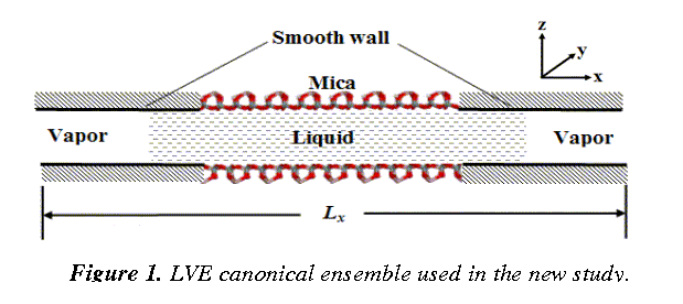
Thus, great efforts have been invested on the development of a completely new molecular ensemble ¾ the liquid-vapor extended (LVE) canonical ensemble that allows for liquid molecules being squeezed out during the surface normal approach. Details of this molecular ensemble are illustrated in Fig.1. The mica surfaces are connected to structureless smooth walls on the two sides along the x-direction. The interaction between the smooth wall and fluid molecules is not critical, since we are interested in the central region where the variation of hydration force and dynamics of fluid molecules during squeeze-out are of our central interest. For simplicity, we employ the 9-3 Lennard-Jones (LJ) surface potential. The model system, by introducing liquid-vapor (LV) interfaces, circumvents sophisticated pressure calculations for strongly inhomogeneous systems (which often leads to errors and artifacts), as well as the scaling of the coordinates of the molecular system in conventional NPT (constant temperature T and pressure p) ensemble.
 |
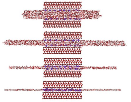
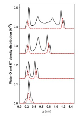
Primary Results ¾ Demonstration of the stability of liquid-vapor (LV) interface and the existence of repulsive hydration forces in the surface force experiments through a newly developed LVE molecular ensemble Figure 2 shows the dynamic squeeze out of a water droplet (1152 water molecules) confined between two mica surfaces. In (a), water droplet is compressed from a distance of D = 1.7 nm to a very thin hydration layer (D ~ 0.5 nm). At 298 K, it is seen that water LV interfaces are rough, but stable. In (b), the density distributions of water O (black solid lines) and K+ ions (red dashed lines) along the normal (z-) direction in the mica pore are shown. These water density peaks correspond to different hydration layers. The simulation box lengths in the x-, y-, and z-directions are: 300, 36.06, and 50 Ă, respectively. The very large (30nm) distance in the x-direction will allow water molecules being freely squeezed out during compression. To accurately calculate Ewald summation for the long-range electrostatic interactions, 4800 vectors are used in reciprocal space.
 | |||
 | |||
(a) (b)
Figure 2. Dynamic evolution of hydration layers.
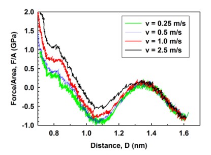
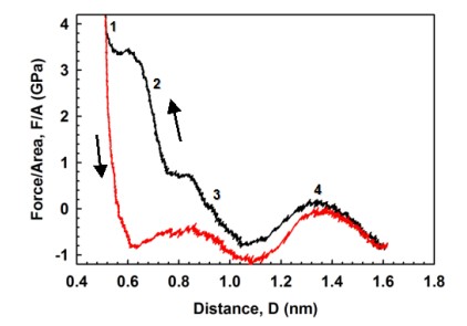 Figure 3(a) shows the variations of hydration force between mica surfaces in a water droplet (1152 water molecules). The approach speed is v=1 m/s. At four water layer thickness (D ~ 1.3 nm), there is already a repulsive hydration pressure of 0.2GPa. The maximum pressure at one water layer is about 4 GPa. However, the current molecular dynamics (MD) model has not yet included the effect of anions (e.g., Cl-) in electrolyte solutions, and will be explored in the next step. Figure 3(b) shows the rate-dependent phenomenon of hydration forces. For D > 1.0 nm films, there is essentially no difference of hydration force between v = 0.25 and 0.5 m/s, indicating that hydrodynamic effect is eliminated. Using a “steered diffusion” model, the critical normal speed predicted to eliminate hydrodynamic effect in surface force measurements should be in the order of a few nm/s.
 |
(a) (b)
Figure 3. Variations of hydration forces.