Reports: AC8
47782-AC8 The Role of Erosion at the Head of Turbidity Currents - Experiments and Theory
Introduction:
Suspension currents are ubiquitous in nature. They include avalanches, sand storms and deep-sea sediment slides. They self-sustain by maintaining a density difference with the surrounding ambient fluid by eroding and suspending particles from the ground. We investigate them with experiments, theory and numerical simulations. Our analysis of these flows is aimed at establishing how the characteristic shape of the current's head changes as a function of density difference, which in itself depends upon the basal erosion rate.
Experimental Setup:
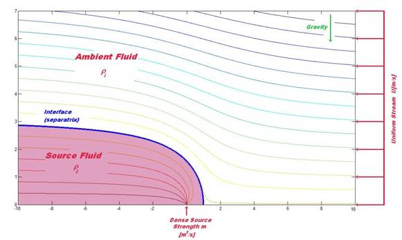
Figure 1: Rankine half body schematic diagram. Uniform
velocity U [m/s], source strength m [m^2/s] (volume flowrate per unit
width).
We have built a water flume experiment with uniform stream and isotropic
source flow. To reach high Reynolds numbers while minimizing parasitic eddies
in the main flow, we have installed a honeycomb mesh section that reduces
upstream turbulence. Our experiments
inject a dense solution containing a fluorescent tracer to identify its motion.
The dense fluid injection is isotropic and distributes uniformly both radially
and longitudinally. To ensure uniformity of the source flow, we are installing
a valve system containing small tubes to feed into the injection nozzle.
Maintaining the source fluid injection as two dimensional is a critical
part of the experimental procedure. To that end, we installed a new pump
driving the source fluid at its optimum flow rate, such that the main flume
flow rate is independent from potential head changes that can cause
oscillations, thus maintaining the position of the dense front at a stable
location. We also created a model of the flume that predicts pressure losses in
the flow in terms of flow rate.
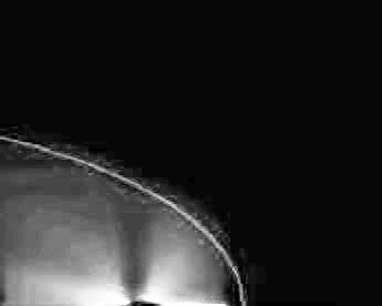
Figure 2: Time-averaged composite of 500 photographs
of the Rankine half body in experiments with superimposed theoretical solution.
Conditions are U=15 cm/s and m=0.047
m^2/s, for water and fluorescein.
We further improved our image acquisition system with a parabolic mirror
and high-power light source. These ensure that a light sheet of constant cross
section is achieved during each experiment. Camera positioning has also been
optimized to produce images with repeatable concentration scale from flume
data.
Theory:
We have developed a theory based upon the polar coordinate solution to
the Laplace equation. In inviscid flow theory, the Rankine half body is created
by inserting an isotropic source into a uniform stream. We perturb the
streamfunction by introducing a small density variation between the ambient and
source fluid. This causes small variations in both the shape of the interface
between the fluids and the velocity and pressure on either side of this
interface.
The front is located at the zeroth streamline. Taking the source fluid
alone, we can determine the equation for the non dimensional interface location
Rsep based upon the non-dimensional streamfunction Psi(Eq1),
Eqn 1
Eqn 2
where r is the radial dimension, theta is
the angle in polar coordinates, m is a measure of the
non-dimensional source strength and B1 is a coefficient
calculated by our solution scheme.
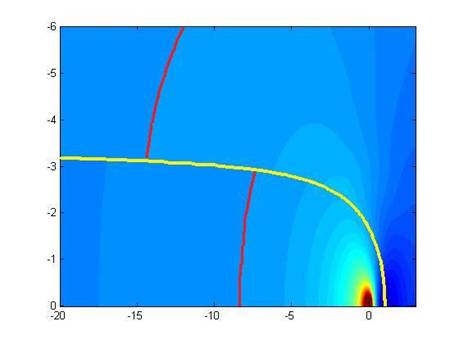
Our analysis reveals a discontinuous velocity profile at the
fluid interface, pointing towards Kelvin-Helmholtz instabilities. Figure 3
illustrates the jump in fluid velocity that occurs across the interface for a
given density difference.
Figure 3: Dimensionless velocity field for the density
perturbed Rankine half body interface outlined in yellow. Note the shear layer
at the interface illustrated by the red velocity contour.
Simulations
We employ ANSYS Fluent commercial CFD software to create a
model of the Rankine half body. The simulation reproduces the
analytically-derived position of the interface and the velocity field.
We pinpoint the location of the separatrix by initializing
the source and ambient fluids as two separate immiscible flows. This multiphase
model uses an interface tracking method to determine the front location as a
function of time until the final steady state solution is produced. A density
change can be created by changing the properties of either distinct fluid
phases. Preliminary results of density difference analysis from this simulation
indicate good agreement with the theory at low density differences.
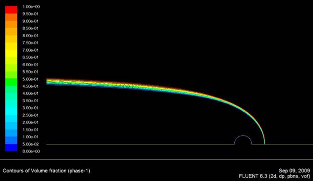
Figure 4: Rankine half body
produced by simulating two immiscible fluids from the main stream and source.
The interface between ambient and source fluid is shown as a narrow peak in the
2D contours of phi(1-phi), where phi is the volume fraction of one
of the fluids.
Future Work:
We are designing and installing a new control valve system
for the dense fluid injection. This will increase the uniformity of our flow
rates from the source. We will also introduce a basal slope angle to the flume
and create density differences in these experiments. We are presently carrying
out simulations to examine both the effects of a combined slope and density
difference. We will also adapt the boundary conditions of the simulation to
model viscous floor effects. Introducing the effects of viscosity and turbulent
closures into the model will give us greater insight into experimental observations.
![]()
![]()