Reports: AC10
47267-AC10 Fundamental Studies of Nano-Scale Catalysts In Direct Internal Reforming Solid Oxide Fuel Cells
This project provided an important opportunity to explore fundamental properties of new fuel cell electrodes -- it is difficult to obtain funding for such basic studies. We also developed the conductivity relaxation method in our lab, which will be very useful for future investigations. The project also gave a post-doctoral student, Jason Nicholas, an excellent opportunity to broaden his horizons to an area much different than his doctoral work.
The following summarizes the key results from the completed project, organized according to the originally proposed objectives (in italics):
1) Successfully synthesize nano-catalyst anode materials in samples designed for three different types of measurements. Three types of anode powders were by synthesized by solid state reaction: (La0.8Sr0.2)(Cr1-xRux)O3-d (LSCrRu), (La0.8Sr0.2)(Cr1-xCox)O3-d (LSCrCo), and (La0.8Sr0.2)(Cr1-yPdy)O3-d (LSCrPd) (See Figure 1). The latter two were tried instead of the originally proposed Rh-based compound, based on dramatic increases in the price of Rh. The new Pd-doped composition was particularly interesting since, as described below, it produced the lowest polarization resistance of any of the anodes and exhibited excellent sulfur tolerance. Interestingly, however, the material did not appear to be phase pure, but rather consisted of a mixture of the perovskite phase (similar major peaks as a perovskite (La0.8Sr0.2)CrO3-d (LSCr) standard in Figure 1) and a La4PdO7 phase (additional small peaks in Figure 1).
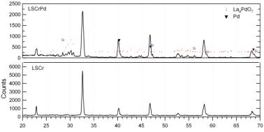
Figure 1. X-ray scans of LSCr (bottom) and LSCrPd (top) un-reduced powder sample. A Si standard was used to align the LSCrPd scan and the secondary phase appears to be La4PdO7.
2) Characterize anode electrochemical processes as affected by catalyst nano-clusters using electrochemical impedance spectroscopy (EIS). EIS was used for characterization of the anodes. While the LSCrCo did not show especially desirable SOFC anode electrochemical properties, the new LSCrPd compound yielded excellent anode performance. Figure 2 shows the current-voltage-power results, indicating a maximum power density of 0.58 W/cm2 at 800C, and EIS data showing an anode polarization resistance in humidified hydrogen at 800C < 0.2 Wcm2. These results are better than those obtained for the LSCrRu compound. The high performance can be explained from the nucleation of Pd-rich particles throughout the oxide material upon exposure to hydrogen, as shown in TEM images (Figure 3).
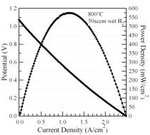
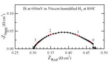
Figure 2. Current voltage characteristics (left) and impedance spectra (right) from a cell with an LSCrPd anode.
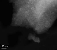
Figure 3. STEM micrograph of LSCrPd raw powder that has been reduced in humidified H2 at 800°C.
3) Utilize conductivity relaxation experiments to directly measure how nano-scale metal particles affect key rate-limiting surface processes. Conductivity relaxation measurements were found to be problematic for these materials, since the porous bulk pellets used for the measurements were relatively weak and typically cracked upon reduction in fuel. Thus, only a limited set of results were obtained. Figure 4 shows an example of the voltage at constant current for a LSCrRu pellet measured in CO/CO2 mixtures. The initial decrease in (negative) voltage is the sample equilibrating with an effective oxygen partial pressure PO2 = 10-17 atm. At ~ 6000 s, the CO/CO2 ratio was changed to yield PO2 = 10-18 atm, resulting in a rapid initial voltage increase, followed by a slower voltage decrease. The first change was the conductivity relaxation due the change in LSCrRu oxygen content, which gives a measure of oxygen reaction rate. The second change was believed to be a result of Ru nucleation on particle surfaces changing the sample conductivity. Finally, the gas composition was changed again (at ~ 14000 s) in order to return the PO2 to 10-17 atm, yielding a decrease in voltage. The measured relaxation times have yielded oxygen surface exchange rates on LSCrRu surfaces.
Figure 4. Voltage versus time at a constant current of 20 mA with changes in CO/CO2 ratio.
4) Quantify reforming kinetics for various nano-cluster morphologies and fuels. The catalytic measurements on the LSCrRu anodes showed little or no reforming activity. This was explained by the very small volume of Ru metal in the thin (~ 10 mm) anode layer. This interpretation was verified by testing reforming on a thick LSCrRu pellet (Figure 5). It showed better, but still relatively low, reforming activity at temperature > 700C as indicated by a decrease in CH4 and CO2 and an increase in H2 and CO.
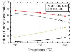
Figure 5. Reactor exhaust data for a 0.44g pellet exposed to 25sccm CH4 and 25sccm CH4.
It is interesting that thin-layer nano-catalysts were very effective for promoting anode electrochemistry, which occurs in a very thin layer near the anode/electrolyte interface, but were less effective for reforming which presumably requires a larger total amount of catalyst surface area. These results help explain prior measurements showing poor performance of these anodes in methane-steam or methane-CO2 mixtures; little or no hydrogen was produced by reforming, and the anode apparently was not active for direct oxidation of methane.
5) Characterize SOFCs containing nano-cluster anodes and separate catalyst layers to determine performance and stability in a range of fuel mixtures. Based on the poor reforming activity of the anodes, the addition of a separate catalyst material was used to produce hydrogen that could be utilized by the anode. A new catalyst material, Ni-Sn, was utilized and found to provide good reforming activity; the Sn component was found to provide improved resistance to coking. This composition is preferable to the precious-metal reforming catalysts used previously in catalyst-assisted SOFCs, due to their much lower cost. Overall, this strategy and catalyst material proved to be quite effective, as good SOFC performance was achieved in methane-CO2 fuel mixtures using a catalyst layer. Figure 6 shows that the maximum power density with CH4-CO2 fuel increased dramatically due to the addition of the catalyst. This was in spite of the additional concentration polarization introduced by the thick catalyst support used in these experiments, as indicated by the reduced power density of the cell operated with hydrogen (Figure 6).
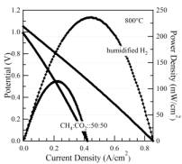
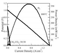
Figure 5. Current voltage characteristics for an LSCrRu-GDC cell operated with the Ni-Sn catalyst (left) and with no catalyst (right) on humidified hydrogen and a 50:50 ratio of CH4 and CO2.