Reports: AC9
48276-AC9 Yield Stress of Complex Fluids: A Numerical Study for a Concentric Cylinder Geometry with Slotted Rotor
1. Background
Wall slip effects frequently present problems in rheological experiments, especially when dealing with suspensions. Wall and sample interactions can result in slip effects or in stress reduction. Smooth walls, high shear rate gradients and low flow rates increase the probability of wall slip effects.
So far in the present study, we used an idealized Bingham fluid. The constitutive equation can be written as:
The difficulty in applying the Bingham model is mainly due to the discontinuity in the constitutive relations. The regularized Bingham model (Papanastasiou, 1987) can be written as:
where m is a parameter related to the transition between the solid and fluid regimes. In the present study, parameter m is chosen to be equal to 100, which proves sufficiently large to simulate Bingham fluids under the considered flow conditions.
2. Numerical method
We employed a Lagrangian approach, smoothed particle hydrodynamics (SPH), in the numerical computation. The SPH approach removes the difficulties associated with convective terms and allows one to tackle fluid and solid flow problems involving large deformation and free surfaces in a relatively natural way.
Discretized SPH equations
The SPH method is based on the following integral
where f(x) is an arbitrary function, W is the weighting function, and h is a parameter that effectively controls the width of the weighting function with
The weighting function approaches the delta function as the parameter h approaches zero.
Boundary conditions
The solid material forming the boundary is filled with equi-spaced virtual boundary particles. Boundary particles contribute to the usual SPH expressions for velocity, pressure and stress gradients. In this case, for every solid boundary particle j, a normal distance dj to the boundary surface is defined. This is used to construct a tangent plane to the surface, and consequently the normal distance di to this plane for a selected fluid particle i .
Integration Scheme
A predictor-corrector scheme is used that offers second order accuracy in time. The particle accelerations are computed and the new fluid particle velocities and positions are determined via a two-step integration.
Setup of computation domain
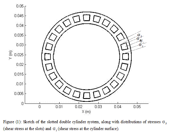
The diameters of the inner and outer walls of the geometry cup, inner and outer surfaces of the rotator are 0.017m, 0.023m, 0.0185 and 0.0215m, respectively. There totally 24 uniformly distributed slots in the rotor as shown in Figure (1). Following Zhu and De Kee (2007), the ratio of the non-slotted area over the total area is chosen to be 0.6.
Numerical results and discussions
A 2D geometry is considered here. The shape and position of the shearing surface is considered independent of the shear stress profile near the upper and lower ends.
Shear stress profiles
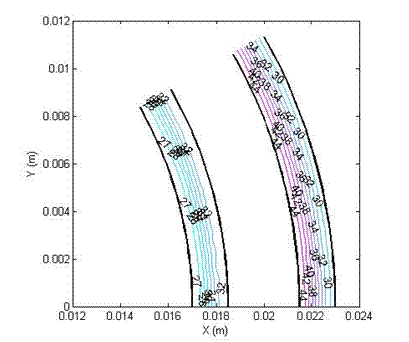
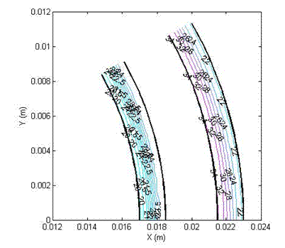
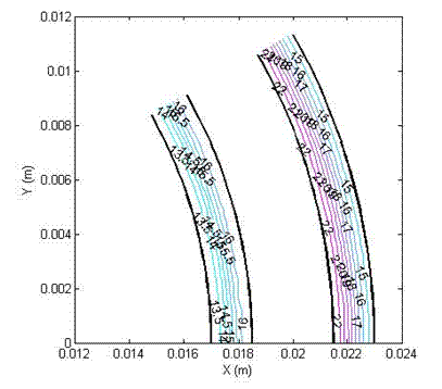
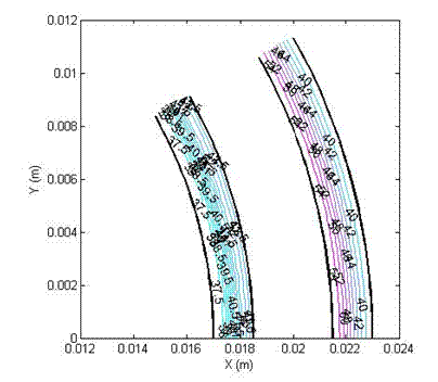
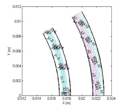
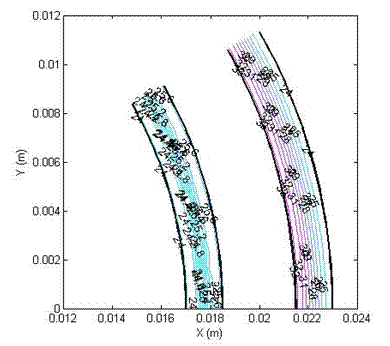
Figures (2 a-c) show the shear stress of a Newtonian fluid while
Figures (3a-c) show the shear stress of a yield stress fluid with a yield
stress of 20 Figure (2a): Shear stress profile in a double cylinder
(non-slotted), with yield stress: 0 Pa (Newtonian), viscosity 5 Pa.s, angular velocity 1 (1/s) and slip velocity 0.
Figure (2b): Shear stress profile in a double cylinder
(non-slotted), with yield stress 0 Pa (Newtonian), viscosity 5 Pa.s, angular velocity 1 (1/s) and slip velocity 25%.
Figure (2c): Shear stress profile in a double cylinder
(non-slotted), with yield stress 0 Pa (Newtonian), viscosity 5 Pa.s, angular velocity 1 (1/s) and slip velocity 50%.
Figure (3a): Shear stress profile in a double cylinder
(non-slotted), with yield stress 20Pa, viscosity 5 Pa.s,
angular velocity 1 (1/s) and slip velocity 0.
Figure (3b): Shear stress profile in a double cylinder
(non-slotted), with yield stress 20 Pa, viscosity 5 Pa.s,
angular velocity 1 (1/s) and slip velocity 25%.
Figure (3c): Shear stress profile in a double cylinder
(non-slotted), with yield stress 20 Pa, viscosity 5 Pa.s,
angular velocity 1 (1/s) and slip velocity 50%.
Shear stress
reduction due to slip and the effect of slots in the geometry
In the numerical simulation, we assume that slip
occurs only at the interface between the walls of the rotor and the fluid. The
shear stress reduction due to the slip is less for yield stress fluids than for
Newtonian fluids. This trend is more prominent when the relatively slip is
higher. It is observed that for both Newtonian and yield stress fluids, the
wall slip effects are reduced compared to that in the non-slotted case. The
relative improvement for the case with a 25% slip velocity boundary condition
is about 5% and the improvement for the case with a 50% slip boundary condition
is about 11%.


